
Page 84 - Handbook of Materials Failure Analysis
P. 84
78 CHAPTER 4 Creep damage of high alloyed reformer tubes
top, supply energy for the endothermic reaction, heating hydrocarbon and steam
from the inlet temperature ( 500 °C) up to the outlet temperature reached by the
reaction products ( 900 °C).
The reformer tubes, heated from the outside, have nominal internal diameter of
101.6 mm, wall thickness of 10.5 mm, and length of 12.8 m; they were designed to
work at 950 °C with 32.8 bar of pressure for minimum 90,000 h and constructed in
three pieces produced by centrifugal casting and then joined by gas tungsten arc
welding (GTAW) (details on this procedure are given in [32]).
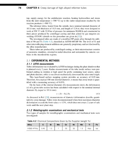
The investigated tubes are made of a modified HP grade alloy through the addi-
tion of Nb and Ti (Table 4.2), classified as ASTM 608 HP-Nb. The level of Ti and
other microalloying element additions are generally proprietary and not disclosed by
the alloy manufacturer.
These tubes are produced by centrifugal casting, so their microstructure consists
of austenitic dendrites, oriented in radial direction and surrounded by eutectic car-
bides in the interdendritic regions.
2.1 EXPERIMENTAL METHODS
2.1.1 LOTIS measurements
Tubes deformation was evaluated by LOTIS technique during the plant shutdown that
is planned every 2 years. Radius measurements of the tube inside surface were per-
formed putting in rotation at high speed the probe containing laser source, optics
and photo detector, while it was driven mechanically downward the tubes total length.
This laser-based surface mapping system provides an accuracy of 0.05 mm.
Therefore, for a typical 100 mm internal diameter, it means that creep strain is quan-
tified with a measuring accuracy of 0.05%.
On the basis of the internal diameter (D i ) measurements (mm), the deformation
(ε) of a given tube section has been calculated with respect to the nominal internal
diameter D 0 (equal to 101.6 mm):
ð
ε ¼ D i D 0 Þ=D 0 (4.3)
As discussed in Ref. [30], measurements of diameter deformation describe quanti-
tatively creep damage. Tubes were decommissioned when their maximum diameter
deformation exceeds the limit value ε¼1.5%, which does not ensure 2 years of safe
work until the next plant stop.
2.1.2 Metallographic examinations and mechanical tests
Two types of samples for metallographic examinations and mechanical tests were
investigated:
Table 4.2 Chemical Compositions Given by the Supplier (weight %)
Alloy C Si Mn Cr Ni Nb Ti Fe
A 608 HP-Nb 0.45 1.5 1 25 35 1.5 Add. bal