
Page 85 - Handbook of Materials Failure Analysis
P. 85
2 Case History 79
- Type A: samples of the A 608 HP-Nb grade, taken from a tube in cast condition,
as supplied.
- Type B: samples of the A 608 HP-Nb grade taken from segments with different
values of the internal diameter, taken from tubes decommissioned after long-time
service.
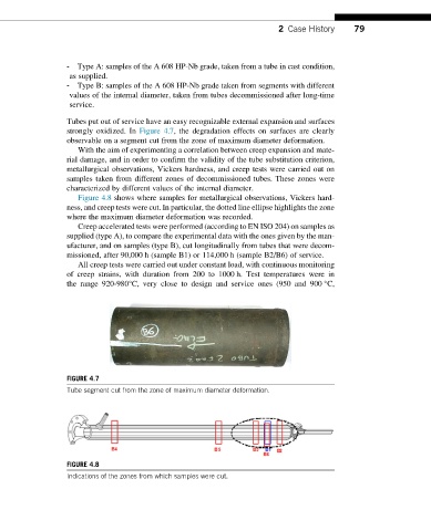
Tubes put out of service have an easy recognizable external expansion and surfaces
strongly oxidized. In Figure 4.7, the degradation effects on surfaces are clearly
observable on a segment cut from the zone of maximum diameter deformation.
With the aim of experimenting a correlation between creep expansion and mate-
rial damage, and in order to confirm the validity of the tube substitution criterion,
metallurgical observations, Vickers hardness, and creep tests were carried out on
samples taken from different zones of decommissioned tubes. These zones were
characterized by different values of the internal diameter.
Figure 4.8 shows where samples for metallurgical observations, Vickers hard-
ness, and creep tests were cut. In particular, the dotted line ellipse highlights the zone
where the maximum diameter deformation was recorded.
Creep accelerated tests were performed (according to EN ISO 204) on samples as
supplied (type A), to compare the experimental data with the ones given by the man-
ufacturer, and on samples (type B), cut longitudinally from tubes that were decom-
missioned, after 90,000 h (sample B1) or 114,000 h (sample B2/B6) of service.
All creep tests were carried out under constant load, with continuous monitoring
of creep strains, with duration from 200 to 1000 h. Test temperatures were in
the range 920-980°C, very close to design and service ones (950 and 900 °C,
FIGURE 4.7
Tube segment cut from the zone of maximum diameter deformation.
FIGURE 4.8
Indications of the zones from which samples were cut.