
Page 78 - Handbook of Materials Failure Analysis
P. 78
72 CHAPTER 4 Creep damage of high alloyed reformer tubes
austenitic microstructure that provides good mechanical strength and creep resis-
tance according to its morphology [7].
Grain size and shape depend mainly on cooling rate during casting solidification.
Generally, it can be stated that creep-resistant tubes reach the highest quality when
coarse columnar dendrites, radially oriented, affect the entire cross-section of the
casting wall [8].
Mechanical strength at high temperatures is ensured by a dispersion of hard
deformation-resistant Cr carbide particles in the interdendritic regions, consequently
creep behavior depends on their stability [9].
Unfortunately during long-term service at high temperature, material microstruc-
ture undergoes degradation phenomena because carbides changes their morphology
tending to particles coarsening in order to minimize surface energy [10].
In literature [11] it was shown, through aging experiments, that after short-term
permanence at temperature of 900 °C the material microstructure is generally sub-
jected to degradation that accumulates as time progresses: carbon precipitation
occurs in the early stages, then coalescence and coarsening of carbides result in
embrittlement and reduction of strength. Last, further degradation [12] may lead
to creep cavities, cavity coalescence, interdendritic microcracks, and final propaga-
tion of macrocracks during the tertiary stage of creep.
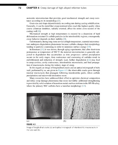
In this regard, an image of longitudinal cracks and an optical micrograph of tube
wall, performed by us, are given in Figure 4.3: the observable cracks grow through
internal microcracks that propagate following interdendritic paths, where carbide
precipitation and microvoid nucleation occur.
Many researches have addressed their effort to optimize chemical composition
and delay creep damage phenomena that occur inevitably: additional strengthening
is provided by solid-solution of transition metals such as niobium in the HP-Nb alloy,
where the primary NbC carbides have a lamellar morphology [13].
(a) (b)
FIGURE 4.3
Image of longitudinal cracks (a) and optical micrograph of interdendritic macrocracks in
the tube wall (b).