
Page 104 - Handbook of Structural Steel Connection Design and Details
P. 104
Design of Connections for Axial, Moment, and Shear Forces
Design of Connections for Axial, Moment, and Shear Forces 89
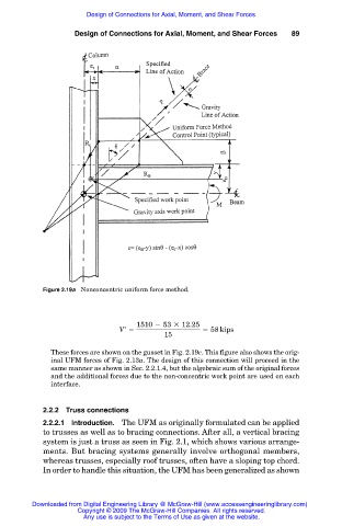
Figure 2.19a Nonconcentric uniform force method.
1510 2 53 3 12.25
V 5 58 kips
15
These forces are shown on the gusset in Fig. 2.19c. This figure also shows the orig-
inal UFM forces of Fig. 2.13a. The design of this connection will proceed in the
same manner as shown in Sec. 2.2.1.4, but the algebraic sum of the original forces
and the additional forces due to the non-concentric work point are used on each
interface.
2.2.2 Truss connections
2.2.2.1 Introduction. The UFM as originally formulated can be applied
to trusses as well as to bracing connections. After all, a vertical bracing
system is just a truss as seen in Fig. 2.1, which shows various arrange-
ments. But bracing systems generally involve orthogonal members,
whereas trusses, especially roof trusses, often have a sloping top chord.
In order to handle this situation, the UFM has been generalized as shown
Downloaded from Digital Engineering Library @ McGraw-Hill (www.accessengineeringlibrary.com)
Copyright © 2009 The McGraw-Hill Companies. All rights reserved.
Any use is subject to the Terms of Use as given at the website.