
Page 109 - Handbook of Structural Steel Connection Design and Details
P. 109
Design of Connections for Axial, Moment, and Shear Forces
94 Chapter Two
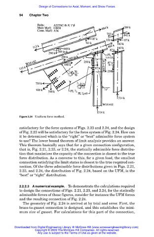
Figure 2.24 Uniform force method.
satisfactory for the force systems of Figs. 2.23 and 2.24, and the design
of Fig. 2.23 will be satisfactory for the force system of Fig. 2.24. How can
it be determined which is the “right” or “best” admissible force system
to use? The lower bound theorem of limit analysis provides an answer.
This theorem basically says that for a given connection configuration,
that is, Fig. 2.21, 2.23, or 2.24, the statically admissible force distribu-
tion that maximizes the capacity of the connection is closest to the true
force distribution. As a converse to this, for a given load, the smallest
connection satisfying the limit states is closest to the true required con-
nection. Of the three admissible force distributions given in Figs. 2.21,
2.23, and 2.24, the distribution of Fig. 2.24, based on the UFM, is the
“best” or “right” distribution.
2.2.2.3 A numerical example. To demonstrate the calculations required
to design the connections of Figs. 2.21, 2.23, and 2.24, for the statically
admissible forces of these figures, consider for instance the UFM forces
and the resulting connection of Fig. 2.24.
The geometry of Fig. 2.24 is arrived at by trial and error. First, the
brace-to-gusset connection is designed, and this establishes the mini-
mum size of gusset. For calculations for this part of the connection,
Downloaded from Digital Engineering Library @ McGraw-Hill (www.accessengineeringlibrary.com)
Copyright © 2009 The McGraw-Hill Companies. All rights reserved.
Any use is subject to the Terms of Use as given at the website.