
Page 108 - Handbook of Structural Steel Connection Design and Details
P. 108
Design of Connections for Axial, Moment, and Shear Forces
Design of Connections for Axial, Moment, and Shear Forces 93
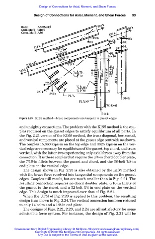
Figure 2.23 KISS method—brace components are tangent to gusset edges.
and unsightly connections. The problem with the KISS method is the cou-
ples required on the gusset edges to satisfy equilibrium of all parts. In
the Fig. 2.21 version of the KISS method, the truss diagonal, horizontal,
and vertical components are placed at the gusset edge centroids as shown.
The couples 15,860 kips-in on the top edge and 3825 kips-in on the ver-
tical edge are necessary for equilibrium of the gusset, top chord, and truss
vertical, with the latter two experiencing only axial forces away from the
connection. It is these couples that require the 3/4-in chord doubler plate,
the 7/16-in fillets between the gusset and chord, and the 38-bolt 7/8-in
end plate on the vertical edge.
The design shown in Fig. 2.23 is also obtained by the KISS method
with the brace force resolved into tangential components on the gusset
edges. Couples still result, but are much smaller than in Fig. 2.21. The
resulting connection requires no chord doubler plate, 5/16-in fillets of
the gusset to the chord, and a 32-bolt 3/4-in end plate on the vertical
edge. This design is much improved over that of Fig. 2.21.
When the UFM of Fig. 2.20 is applied to this problem, the resulting
design is as shown in Fig. 2.24. The vertical connection has been reduced
to only 14 bolts and a 1/2-in end plate.
The designs of Figs. 2.21, 2.23, and 2.24 are all satisfactory for some
admissible force system. For instance, the design of Fig. 2.21 will be
Downloaded from Digital Engineering Library @ McGraw-Hill (www.accessengineeringlibrary.com)
Copyright © 2009 The McGraw-Hill Companies. All rights reserved.
Any use is subject to the Terms of Use as given at the website.