
Page 106 - Handbook of Structural Steel Connection Design and Details
P. 106
Design of Connections for Axial, Moment, and Shear Forces
Design of Connections for Axial, Moment, and Shear Forces 91
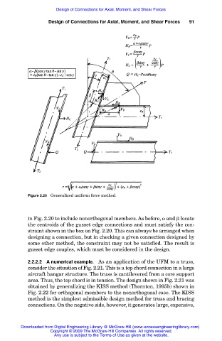
Figure 2.20 Generalized uniform force method.
in Fig. 2.20 to include nonorthogonal members. As before, and locate
the centroids of the gusset edge connections and must satisfy the con-
straint shown in the box on Fig. 2.20. This can always be arranged when
designing a connection, but in checking a given connection designed by
some other method, the constraint may not be satisfied. The result is
gusset edge couples, which must be considered in the design.
2.2.2.2 A numerical example. As an application of the UFM to a truss,
consider the situation of Fig. 2.21. This is a top chord connection in a large
aircraft hangar structure. The truss is cantilevered from a core support
area. Thus, the top chord is in tension. The design shown in Fig. 2.21 was
obtained by generalizing the KISS method (Thornton, 1995b) shown in
Fig. 2.22 for orthogonal members to the nonorthogonal case. The KISS
method is the simplest admissible design method for truss and bracing
connections. On the negative side, however, it generates large, expensive,
Downloaded from Digital Engineering Library @ McGraw-Hill (www.accessengineeringlibrary.com)
Copyright © 2009 The McGraw-Hill Companies. All rights reserved.
Any use is subject to the Terms of Use as given at the website.