
Page 165 - Handbook of Structural Steel Connection Design and Details
P. 165
Design of Connections for Axial, Moment, and Shear Forces
150 Chapter Two
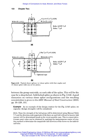
Figure 2.54 Typical shear splices: (a) shear splice with four angles and
(b) shear splice with one or two plates.
between the group centroids, on each side of the splice. This will be the
case for a shop-bolted–field-bolted splice as shown in Fig. 2.54b. A good
discussion on various shear splice configurations and the resulting
eccentricities is given in the AISC Manual of Steel Construction (2005)
pp. 10–129, 131.
Example As an example of the design routine for the Fig. 2.54b splice, its
capacity (design strength) will be calculated.
Bolts. Since the strength of the bolt group will be determined using Manual Table
7-7 and the direction and magnitude of the force on each bolt will not be known, bolt
tearout will be determined based on the worst possible case. This is conservative.
A more exact value can be obtained by applying the instantaneous center of rota-
tion method to determine the magnitude and direction of the forces on the individ-
ual bolts.
Downloaded from Digital Engineering Library @ McGraw-Hill (www.accessengineeringlibrary.com)
Copyright © 2009 The McGraw-Hill Companies. All rights reserved.
Any use is subject to the Terms of Use as given at the website.