
Page 170 - Handbook of Structural Steel Connection Design and Details
P. 170
Design of Connections for Axial, Moment, and Shear Forces
Design of Connections for Axial, Moment, and Shear Forces 155
Interestingly, even a standard shear tab may not provided adequate tor-
sional restraint in this instance. The required thickness of a standard tab
with a 3-in distance from the bolt line to the weld can be calculated as:
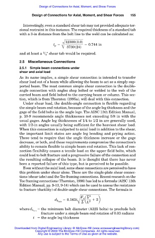
12300s3.0d
t 5 3 5 0.744 in
p
B 3730s24d
3
and at least a /
shear tab would be required.
4
2.5 Miscellaneous Connections
2.5.1 Simple beam connections under
shear and axial load
As its name implies, a simple shear connection is intended to transfer
shear load out of a beam while allowing the beam to act as a simply sup-
ported beam. The most common simple shear connection is the double-
angle connection with angles shop bolted or welded to the web of the
carried beam and field bolted to the carrying beam or column. This sec-
tion, which is from Thornton (1995a), will deal with this connection.
Under shear load, the double-angle connection is flexible regarding
the simple beam end rotation, because of the angle leg thickness and the
gage of the field bolts in the angle legs. The AISC 13th Edition Manual,
p. 10-9 recommends angle thicknesses not exceeding 5/8 in with the
usual gages. Angle leg thicknesses of 1/4 to 1/2 in are generally used,
with 1/2-in angles usually being sufficient for the heaviest shear load.
When this connection is subjected to axial load in addition to the shear,
the important limit states are angle leg bending and prying action.
These tend to require that the angle thickness increase or the gage
decrease, or both, and these requirements compromise the connection’s
ability to remain flexible to simple beam end rotation. This lack of con-
nection flexibility causes a tensile load on the upper field bolts, which
could lead to bolt fracture and a progressive failure of the connection and
the resulting collapse of the beam. It is thought that there has never
been a reported failure of this type, but is perceived to be possible.
Even without the axial load, some shear connections are perceived to have
this problem under shear alone. These are the single-plate shear connec-
tions (shear tabs) and the Tee framing connections. Recent research on the
Tee framing connections (Thornton, 1996) has led to a formula (AISC 13th
Edition Manual, pp. 9-13, 9-14) which can be used to assess the resistance
to fracture (ductility) of double-angle shear connections. The formula is
~ 2
F y b
d 5 0.163t ~ a 1 2b
B b L
b min 2
the minimum bolt diameter (A325 bolts) to preclude bolt
where d b min
fracture under a simple beam end rotation of 0.03 radians
t the angle leg thickness
Downloaded from Digital Engineering Library @ McGraw-Hill (www.accessengineeringlibrary.com)
Copyright © 2009 The McGraw-Hill Companies. All rights reserved.
Any use is subject to the Terms of Use as given at the website.