
Page 171 - Handbook of Structural Steel Connection Design and Details
P. 171
Design of Connections for Axial, Moment, and Shear Forces
156 Chapter Two
~
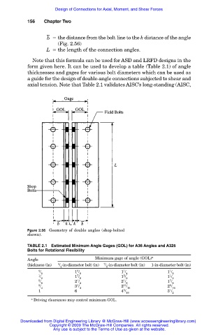
b the distance from the bolt line to the k distance of the angle
(Fig. 2.56)
L the length of the connection angles.
Note that this formula can be used for ASD and LRFD designs in the
form given here. It can be used to develop a table (Table 2.1) of angle
thicknesses and gages for various bolt diameters which can be used as
a guide for the design of double-angle connections subjected to shear and
axial tension. Note that Table 2.1 validates AISC’s long-standing (AISC,
Fgure 2.56 Geometry of double angles (shop-bolted
shown).
TABLE 2.1 Estimated Minimum Angle Gages (GOL) for A36 Angles and A325
Bolts for Rotational Flexibility
Angle Minimum gage of angle (GOL) a
thickness (in) 3 / -in-diameter bolt (in) 7 / -in-diameter bolt (in) 1-in-diameter bolt (in)
4 8
3 / 1 / 1 / 1 /
3
1
1
7
1
1 / 8 1 / 8 1 / 4 1 / 8
5
2 8 8 2
5 / 2 / 2 / 1 /
1
7
1
1
3 / 8 3 / 2 2 / 8 2 / 8
11
5
4 4 16 16
5
1 6 4 / 3 /
1
16 2
a Driving clearances may control minimum GOL.
Downloaded from Digital Engineering Library @ McGraw-Hill (www.accessengineeringlibrary.com)
Copyright © 2009 The McGraw-Hill Companies. All rights reserved.
Any use is subject to the Terms of Use as given at the website.