
Page 172 - Handbook of Structural Steel Connection Design and Details
P. 172
Design of Connections for Axial, Moment, and Shear Forces
Design of Connections for Axial, Moment, and Shear Forces 157
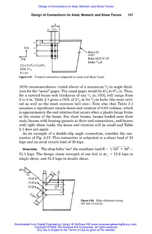
Figure 2.57 Framed connection subjected to axial and shear loads.
5
1970) recommendation (noted above) of a maximum / -in angle thick-
8
1
1
ness for the “usual” gages. The usual gages would be 4 / to 6 / in. Thus,
2 2
1
for a carried beam web thickness of say / in, GOL will range from
2
3
1
2 to 3 in. Table 2.1 gives a GOL of 2 / in for / -in bolts (the most criti-
2 4
cal as well as the most common bolt size). Note also that Table 2.1
assumes a significant simple beam end rotation of 0.03 radians, which
is approximately the end rotation that occurs when a plastic hinge forms
at the center of the beam. For short beams, beams loaded near their
ends, beams with bracing gussets at their end connections, and beams
with light shear loads, the beam end rotation will be small and Table
2.1 does not apply.
As an example of a double-clip angle connection, consider the con-
nection of Fig. 2.57. This connection is subjected to a shear load of 33
kips and an axial tensile load of 39 kips.
2
Shop bolts. The shop bolts “see” the resultant load R 233 1 39 2
51.1 kips. The design shear strength of one bolt is r 15.9 kips in
v
single shear, and 31.8 kips in double shear.
Figure 2.58 Edge distances along
the line of action.
Downloaded from Digital Engineering Library @ McGraw-Hill (www.accessengineeringlibrary.com)
Copyright © 2009 The McGraw-Hill Companies. All rights reserved.
Any use is subject to the Terms of Use as given at the website.