
Page 257 - Handbook of Structural Steel Connection Design and Details
P. 257
Welded Joint Design and Production
242 Chapter Three
The other three systems assume that at some point within the struc-
ture, plastic deformations will occur in members, thus absorbing seis-
mic energy. In this section, no attempt is being made to compare the
relative advantages of one system over another. Rather, the focus will
be placed on the demands on welded connections’ and member behav-
ior with respect to the various systems that may be selected by the
designer.
In the CBF system, the brace member is the one expected to be sub-
ject to inelastic deformations. The welded connections at the termina-
tion of a brace are subject to significant tension or compression loads,
although rotation demands in the connections are fairly low. Designs of
these connections are fairly straightforward, requiring the engineer to
develop the capacity of the brace member in compression and tension.
Recent experiences with CBF systems have reaffirmed the importance
of the brace dimensions (b/t ratio), and the importance of good details
in the connection itself. Problems seem to be associated with under-
sized welds, misplaced welds, missing welds, or welds of insufficient
throat due to construction methods. In order to place the brace into the
building frame, it is common to utilize a gusset plate welded into the
corners of the frame. The brace is slit along its longitudinal axis and
rotated into place. In order to maintain adequate dimensions for field
assembly, it is necessary to oversize the slot in the tube as compared to
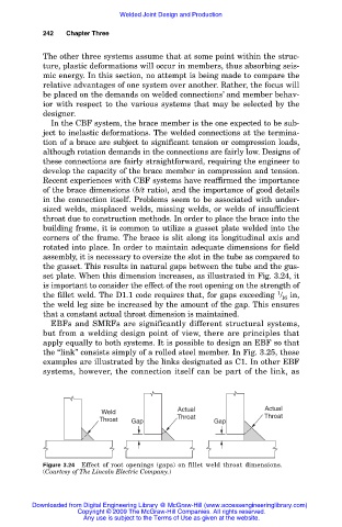
the gusset. This results in natural gaps between the tube and the gus-
set plate. When this dimension increases, as illustrated in Fig. 3.24, it
is important to consider the effect of the root opening on the strength of
1
the fillet weld. The D1.1 code requires that, for gaps exceeding / in,
16
the weld leg size be increased by the amount of the gap. This ensures
that a constant actual throat dimension is maintained.
EBFs and SMRFs are significantly different structural systems,
but from a welding design point of view, there are principles that
apply equally to both systems. It is possible to design an EBF so that
the “link” consists simply of a rolled steel member. In Fig. 3.25, these
examples are illustrated by the links designated as C1. In other EBF
systems, however, the connection itself can be part of the link, as
Weld Actual Actual
Throat Gap Throat Gap Throat
Figure 3.24 Effect of root openings (gaps) on fillet weld throat dimensions.
(Courtesy of The Lincoln Electric Company.)
Downloaded from Digital Engineering Library @ McGraw-Hill (www.accessengineeringlibrary.com)
Copyright © 2009 The McGraw-Hill Companies. All rights reserved.
Any use is subject to the Terms of Use as given at the website.