
Page 258 - Handbook of Structural Steel Connection Design and Details
P. 258
Welded Joint Design and Production
Welded Joint Design and Production 243
d c2 c2 d c2 d c1 d
a b a b b a b b
d c2 c2 d d c2 d c1 d
a b a b b a b b
d c2 c2 d d c2 d c1 d
a b b b a b b
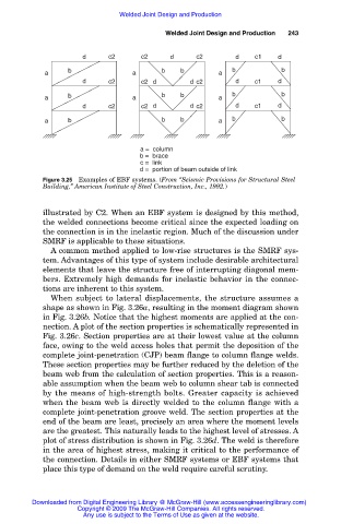
a = column
b = brace
c = link
d = portion of beam outside of link
Figure 3.25 Examples of EBF systems. (From “Seismic Provisions for Structural Steel
Building,” American Institute of Steel Construction, Inc., 1992.)
illustrated by C2. When an EBF system is designed by this method,
the welded connections become critical since the expected loading on
the connection is in the inelastic region. Much of the discussion under
SMRF is applicable to these situations.
A common method applied to low-rise structures is the SMRF sys-
tem. Advantages of this type of system include desirable architectural
elements that leave the structure free of interrupting diagonal mem-
bers. Extremely high demands for inelastic behavior in the connec-
tions are inherent to this system.
When subject to lateral displacements, the structure assumes a
shape as shown in Fig. 3.26a, resulting in the moment diagram shown
in Fig. 3.26b. Notice that the highest moments are applied at the con-
nection. A plot of the section properties is schematically represented in
Fig. 3.26c. Section properties are at their lowest value at the column
face, owing to the weld access holes that permit the deposition of the
complete joint-penetration (CJP) beam flange to column flange welds.
These section properties may be further reduced by the deletion of the
beam web from the calculation of section properties. This is a reason-
able assumption when the beam web to column shear tab is connected
by the means of high-strength bolts. Greater capacity is achieved
when the beam web is directly welded to the column flange with a
complete joint-penetration groove weld. The section properties at the
end of the beam are least, precisely an area where the moment levels
are the greatest. This naturally leads to the highest level of stresses. A
plot of stress distribution is shown in Fig. 3.26d. The weld is therefore
in the area of highest stress, making it critical to the performance of
the connection. Details in either SMRF systems or EBF systems that
place this type of demand on the weld require careful scrutiny.
Downloaded from Digital Engineering Library @ McGraw-Hill (www.accessengineeringlibrary.com)
Copyright © 2009 The McGraw-Hill Companies. All rights reserved.
Any use is subject to the Terms of Use as given at the website.