
Page 271 - Handbook of Structural Steel Connection Design and Details
P. 271
Welded Joint Design and Production
256 Chapter Three
and specifically those that demand inelastic performance, it is appar-
ent that every detail in this region, including weld access hole geome-
try and quality, is a critical variable. Some cracking initiated from weld
access holes in the Northridge earthquake. Whether this was the result
of preexistent cracks that occurred during flange cutting, or the result
of strains that were induced by the shrinkage of the welds during fabri-
cation and/or erection, or simply the concentration of seismically
induced forces that were amplified in these regions, is not known at
this time. It does highlight the importance, however, of paying atten-
tion to all construction details, including weld access holes.
3.9.5 Materials
Base metal. Base metal properties are significant in any type of steel
construction but particularly in structures subject to seismic loading.
While most static designs do not require loading beyond the yield
strength of the material, seismically resistant structures depend on
acceptable material behavior beyond the elastic limit. Although most
static designs attempt to avoid yielding, the basic premise of seismic
design is to absorb seismic energies through yielding of the material.
For static design, additional yield strength capacity in the steel may
be desirable. For applications where yielding is the desired method
for achieving energy absorption, higher than expected yield strengths
have a dramatic negative effect on some designs. This is particularly
important as it relates to connections, both bolted and welded.
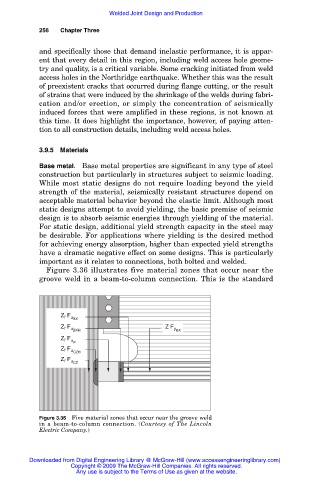
Figure 3.36 illustrates five material zones that occur near the
groove weld in a beam-to-column connection. This is the standard
Z F u BX
f
Z F u BXH Z F y BX
f
Z F u w
f
Z F u CZH
f
Z F u CZ
f
Figure 3.36 Five material zones that occur near the groove weld
in a beam-to-column connection. (Courtesy of The Lincoln
Electric Company.)
Downloaded from Digital Engineering Library @ McGraw-Hill (www.accessengineeringlibrary.com)
Copyright © 2009 The McGraw-Hill Companies. All rights reserved.
Any use is subject to the Terms of Use as given at the website.