
Page 47 - Handbook of Structural Steel Connection Design and Details
P. 47
Fasteners and Welds for Structural Connections
32 Chapter One
particle, and cutting of samples from finished welds. Designers should
specify which welds are to be examined, extent of the examination, and
methods to be used.
1.3.7 Methods for determining strength
of skewed fillet welds
It is often beneficial to utilize skewed single-plate or end-plate shear con-
nections to carry members which run nonorthogonal to their supports.
In such case the welds attaching the connection material to the support
must be designed to accommodate this skew. There are two ways to do
this. The AWS D1.1 Structural Welding Code provides a method to cal-
culate the effective throat for skewed T joints with varying dihedral
angles, which is based on providing equal strength in the obtuse and
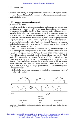
acute welds. This is shown in Fig. 1.15a. The AISC method is simpler,
and simply increases the weld size on the obtuse side by the amount of
the gap, as is shown in Fig. 1.15c.
Both methods can be shown to provide a strength equal to or greater
than the required orthogonal weld size of W. The main difference with
regard to strength is that the AWS method, as given by the formulas in
Fig. 1.16, maintains equal strength in both fillets, whereas the AISC
method increases the strength on the acute side by maintaining a con-
stant fillet size, W = W, while the increased size, W = W + g, on the
a o
obtuse side actually loses strength because of the gap, g. Nevertheless,
it can be shown that the sum of the strengths of these two fillet welds,
W = W and W = W + g, is always greater than the 2W of the required
a o
orthogonal fillets.
It should be noted that the gap, g, is limited to a maximum value of
3 ⁄16 in for both methods.
Φ o Φ o
Φ a 90° 90° Φ a
W o W
W a W W + g
W
3
3
g ≤ 16 " g ≤ "
16
Required
orthogonal
AWS method weld AISC method
(a) (b) (c)
Figure 1.15 Skewed fillet weld sizes required to match strength of required orthogonal
fillets of size W.
Downloaded from Digital Engineering Library @ McGraw-Hill (www.accessengineeringlibrary.com)
Copyright © 2009 The McGraw-Hill Companies. All rights reserved.
Any use is subject to the Terms of Use as given at the website.