
Page 50 - Handbook of Structural Steel Connection Design and Details
P. 50
Fasteners and Welds for Structural Connections
Fasteners and Welds for Structural Connections 35
times the weld size. At this same deformation the longitudinally loaded
weld has only reached about 83 percent of its maximum strength.
To account for this the strength of the weld is calculated as
nx ∑
=
R F wix A wi
ny ∑
=
R F wiy A wi
where A = effective area of weld throat of any ith weld element, in 2
wi
.
(
F = 06 F 1 ( + 050sin 15 ) θ f p)
.
.
wi EXX
F = nominal stress in any ith weld element, ksi
wi
F = x component of stress F
wix wi
F = y component of stress F
wiy wi
=
.
fp() [ p( . − 09 p)] . 03
19
p =∆ ∆ , ratio of element i deformation to its deformation at
/
m
maximum stress
∆ = 0 209(θ + 2) −032 w, deformation of weld element at
.
.
m
maximum stress, in (mm)
∆ = deformation of weld elements at intermediate stress
i
levels, linearly proportioned to the critical deformation
based on distance from the instantaneous center of
rotation, r , in =∆ = r ∆ /r
i i i u crit
∆ = 1 087(θ + 6) −065 w ≤ 0 17 w , deformation of weld element at
.
.
.
u
ultimate stress (fracture), usually in element furthest
from instantaneous center of rotation, in (mm)
w = leg size of the fillet weld, in
r = distance from instantaneous center of rotation to weld
crit
element with minimum ∆ /r ratio, in
u i
1
1
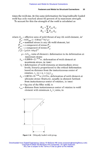
Figure 1.18 Obliquely loaded weld group.
Downloaded from Digital Engineering Library @ McGraw-Hill (www.accessengineeringlibrary.com)
Copyright © 2009 The McGraw-Hill Companies. All rights reserved.
Any use is subject to the Terms of Use as given at the website.