
Page 51 - Handbook of Structural Steel Connection Design and Details
P. 51
Fasteners and Welds for Structural Connections
36 Chapter One
θ = 90°
1.6
θ = 75°
1.4 θ = 60°
θ = 45°
1.2 θ = 30° θ = 15°
θ = 0°
1
R/R o 0.8
0.6 83% of the strength of the
longitudinally loaded weld
0.4
0.2 0.056
0
0 0.02 0.04 0.06 0.08 0.1 0.12 0.14 0.16 0.18
∆/w
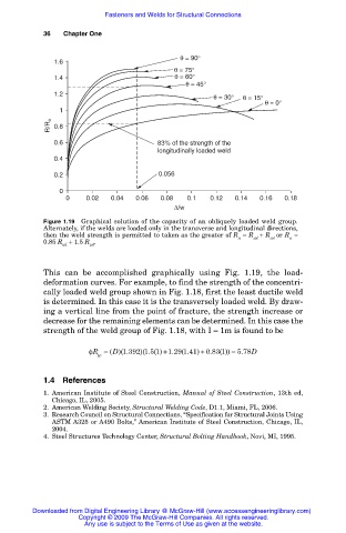
Figure 1.19 Graphical solution of the capacity of an obliquely loaded weld group.
Alternately, if the welds are loaded only in the transverse and longitudinal directions,
then the weld strength is permitted to taken as the greater of R = R + R or R =
wt
n
wl
n
0.85 R + 1.5 R .
wl
wt
This can be accomplished graphically using Fig. 1.19, the load-
deformation curves. For example, to find the strength of the concentri-
cally loaded weld group shown in Fig. 1.18, first the least ductile weld
is determined. In this case it is the transversely loaded weld. By draw-
ing a vertical line from the point of fracture, the strength increase or
decrease for the remaining elements can be determined. In this case the
strength of the weld group of Fig. 1.18, with I = 1m is found to be
1
1
1
0
1
5
φR = ( D)(.392 )(. ( ) + .29 (.41 ) + .83 ( )) = 5..78D
1
1
w
1.4 References
1. American Institute of Steel Construction, Manual of Steel Construction, 13th ed,
Chicago, IL, 2005.
2. American Welding Society, Structural Welding Code, D1.1, Miami, FL, 2006.
3. Research Council on Structural Connections, “Specification for Structural Joints Using
ASTM A325 or A490 Bolts,” American Institute of Steel Construction, Chicago, IL,
2004.
4. Steel Structures Technology Center, Structural Bolting Handbook, Novi, MI, 1995.
Downloaded from Digital Engineering Library @ McGraw-Hill (www.accessengineeringlibrary.com)
Copyright © 2009 The McGraw-Hill Companies. All rights reserved.
Any use is subject to the Terms of Use as given at the website.