
Page 74 - Handbook of Structural Steel Connection Design and Details
P. 74
Design of Connections for Axial, Moment, and Shear Forces
Design of Connections for Axial, Moment, and Shear Forces 59
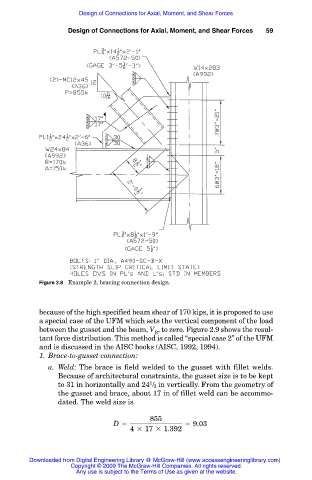
Figure 2.8 Example 2, bracing connection design.
because of the high specified beam shear of 170 kips, it is proposed to use
a special case of the UFM which sets the vertical component of the load
between the gusset and the beam, V , to zero. Figure 2.9 shows the resul-
B
tant force distribution. This method is called “special case 2” of the UFM
and is discussed in the AISC books (AISC, 1992, 1994).
1. Brace-to-gusset connection:
a. Weld: The brace is field welded to the gusset with fillet welds.
Because of architectural constraints, the gusset size is to be kept
1
to 31 in horizontally and 24 / 2 in vertically. From the geometry of
the gusset and brace, about 17 in of fillet weld can be accommo-
dated. The weld size is
855
D 5 5 9.03
4 3 17 3 1.392
Downloaded from Digital Engineering Library @ McGraw-Hill (www.accessengineeringlibrary.com)
Copyright © 2009 The McGraw-Hill Companies. All rights reserved.
Any use is subject to the Terms of Use as given at the website.