
Page 70 - Handbook of Structural Steel Connection Design and Details
P. 70
Design of Connections for Axial, Moment, and Shear Forces
Design of Connections for Axial, Moment, and Shear Forces 55
The shear yield stress (design strength) is F (0.6 F ) 1.0(0.6
v y
36) 21.6 ksi. Since 9.24 21.6, the section has not yielded in shear. The
normal yield stress (design strength) is F F 0.9 (36) 32.4 ksi.
n y
Since 43.0 > 32.4, the yield strength has been exceeded at point A. At this
point, it appears that the design is unsatisfactory (i.e., not meeting AISC
requirements). But consider that the normal stress exceeds yield over only
about 11 inches of the 42 in-long section starting from point A. The remain-
ing 42 11 31 in., have not yet yielded. This means that failure has
not occurred because the elastic portion of the section will constrain
unbounded yield deformations, that is, the deformation is “self-limited.”
Also, the stress of 43.0 ksi is totally artificial! It cannot be achieved in an
elastic–perfectly plastic material with a design yield point of 32.4 ksi.
What will happen is that when the design yield point of 32.4 ksi is reached,
the stresses on the section will redistribute until the design yield point
is reached at every point of the cross section. At this time, the plate will
fail by unrestrained yielding if the applied loads are such that higher
stresses are required for equilibrium.
To conclude on the basis of 43.0 ksi at point A, that the plate has
failed is thus false. What must be done is to see if a redistributed stress
state on the section can be achieved which nowhere exceeds the design
yield stress. Note that if this can be achieved, all AISC requirements will
have been satisfied. The AISC specifies that the design yield stress shall
not be exceeded, but does not specify the formulas used to determine this.
The shear stress f and the axial stress f are already assumed uniform.
v a
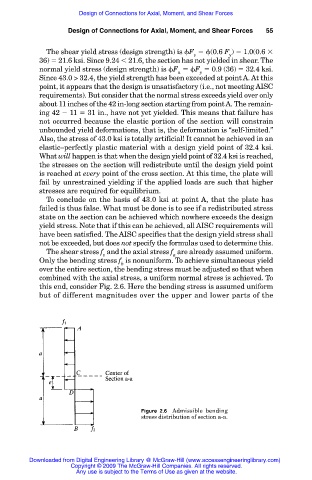
Only the bending stress f is nonuniform. To achieve simultaneous yield
b
over the entire section, the bending stress must be adjusted so that when
combined with the axial stress, a uniform normal stress is achieved. To
this end, consider Fig. 2.6. Here the bending stress is assumed uniform
but of different magnitudes over the upper and lower parts of the
Figure 2.6 Admissible bending
stress distribution of section a-a.
Downloaded from Digital Engineering Library @ McGraw-Hill (www.accessengineeringlibrary.com)
Copyright © 2009 The McGraw-Hill Companies. All rights reserved.
Any use is subject to the Terms of Use as given at the website.