
Page 69 - Handbook of Structural Steel Connection Design and Details
P. 69
Design of Connections for Axial, Moment, and Shear Forces
54 Chapter Two
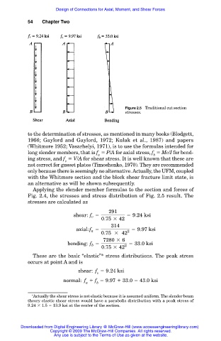
Figure 2.5 Traditional cut section
stresses.
to the determination of stresses, as mentioned in many books (Blodgett,
1966; Gaylord and Gaylord, 1972; Kulak et al., 1987) and papers
(Whitmore 1952; Vasarhelyi, 1971), is to use the formulas intended for
long slender members, that is f P/A for axial stress, f Mc/I for bend-
a b
ing stress, and f V/A for shear stress. It is well known that these are
v
not correct for gusset plates (Timoshenko, 1970). They are recommended
only because there is seemingly no alternative. Actually, the UFM, coupled
with the Whitmore section and the block shear fracture limit state, is
an alternative as will be shown subsequently.
Applying the slender member formulas to the section and forces of
Fig. 2.4, the stresses and stress distribution of Fig. 2.5 result. The
stresses are calculated as
291
shear: f v 5 5 9.24 ksi
0.75 3 42
314
axial: f a 5 2 5 9.97 ksi
0.75 3 42
7280 3 6
bending: f 5 5 33.0 ksi
b
0.75 3 42 2
These are the basic “elastic”* stress distributions. The peak stress
occurs at point A and is
shear: f 9.24 ksi
v
normal: f f 9.97 33.0 43.0 ksi
a b
∗ Actually the shear stress is not elastic because it is assumed uniform. The slender beam
theory elastic shear stress would have a parabolic distribution with a peak stress of
9.24 1.5 13.9 ksi at the center of the section.
Downloaded from Digital Engineering Library @ McGraw-Hill (www.accessengineeringlibrary.com)
Copyright © 2009 The McGraw-Hill Companies. All rights reserved.
Any use is subject to the Terms of Use as given at the website.