
Page 73 - Handbook of Structural Steel Connection Design and Details
P. 73
Design of Connections for Axial, Moment, and Shear Forces
58 Chapter Two
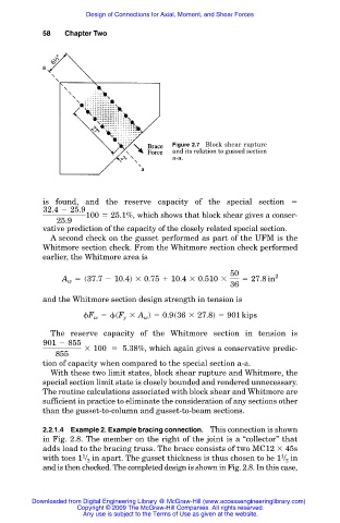
Figure 2.7 Block shear rupture
and its relation to gussed section
a-a.
is found, and the reserve capacity of the special section
32.4 2 25.9
100 5 25.1%, which shows that block shear gives a conser-
25.9
vative prediction of the capacity of the closely related special section.
A second check on the gusset performed as part of the UFM is the
Whitmore section check. From the Whitmore section check performed
earlier, the Whitmore area is
50
A 5 s37.7 2 10.4d 3 0.75 1 10.4 3 0.510 3 5 27.8 in 2
w
36
and the Whitmore section design strength in tension is
F 5 sF 3 A d 5 0.9s36 3 27.8d 5 901 kips
w
y
w
The reserve capacity of the Whitmore section in tension is
901 2 855
3 100 5 5.38%, which again gives a conservative predic-
855
tion of capacity when compared to the special section a-a.
With these two limit states, block shear rupture and Whitmore, the
special section limit state is closely bounded and rendered unnecessary.
The routine calculations associated with block shear and Whitmore are
sufficient in practice to eliminate the consideration of any sections other
than the gusset-to-column and gusset-to-beam sections.
2.2.1.4 Example 2. Example bracing connection. This connection is shown
in Fig. 2.8. The member on the right of the joint is a “collector” that
adds load to the bracing truss. The brace consists of two MC12 45s
1
1
with toes 1 / in apart. The gusset thickness is thus chosen to be 1 / in
2
2
and is then checked. The completed design is shown in Fig. 2.8. In this case,
Downloaded from Digital Engineering Library @ McGraw-Hill (www.accessengineeringlibrary.com)
Copyright © 2009 The McGraw-Hill Companies. All rights reserved.
Any use is subject to the Terms of Use as given at the website.