
Page 68 - Handbook of Structural Steel Connection Design and Details
P. 68
Design of Connections for Axial, Moment, and Shear Forces
Design of Connections for Axial, Moment, and Shear Forces 53
To account for the directional strength increase on fillet welds
5.40
21
5 tan a b 5 44.38
5.53
1.5
5 1.0 1 0.5 sin s44.3d 5 1.29
The required weld size is
7.73
D 5 5 4.30 use a 5/16-in fillet weld
1.392 3 1.29
As a final check, make sure that the beam web can deliver the axial
force to the bolts. The tensile load for 2 bolts is 2 21.6 43.2
kips, and 4 in of the beam web must be capable of delivering this
load, that is, providing a load path. The tensile capacity of 4 in of
the beam web is 4 0.510 0.9 50 91.8 kips > 43.2 kips, ok.
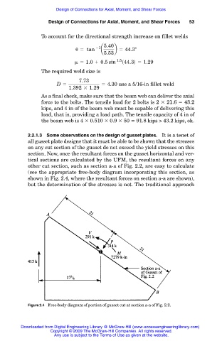
2.2.1.3 Some observations on the design of gusset plates. It is a tenet of
all gusset plate designs that it must be able to be shown that the stresses
on any cut section of the gusset do not exceed the yield stresses on this
section. Now, once the resultant forces on the gusset horizontal and ver-
tical sections are calculated by the UFM, the resultant forces on any
other cut section, such as section a-a of Fig. 2.2, are easy to calculate
(see the appropriate free-body diagram incorporating this section, as
shown in Fig. 2.4, where the resultant forces on section a-a are shown),
but the determination of the stresses is not. The traditional approach
Figure 2.4 Free-body diagram of portion of gusset cut at section a-a of Fig. 2.2.
Downloaded from Digital Engineering Library @ McGraw-Hill (www.accessengineeringlibrary.com)
Copyright © 2009 The McGraw-Hill Companies. All rights reserved.
Any use is subject to the Terms of Use as given at the website.