
Page 205 - Hardware Implementation of Finite-Field Arithmetic
P. 205
m
Operations over GF (2 )—Polynomial Bases 185
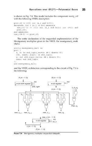
is shown in Fig. 7.4. This model includes the component montg_cell
with the following VHDL description:
prev_c0 <= c(0) xor (a_i and b(0));
datapath: for i in 1 to M-1 generate
new_c(i-1) <= c(i) xor (a_i and b(i)) xor (F(i) and
prev_c0);
end generate;
new_c(M-1) <= prev_c0;
The entity declaration of the sequential implementation of the
Montgomery multiplier given in the VHDL file montgomery_mult.
vhd is
entity montgomery_mult is
port (
a, b: in std_logic_vector (M-1 downto 0);
clk, reset, start: in std_logic;
z: out std_logic_vector (M-1 downto 0);
done: out std_logic
);
end montgomery_mult;
and the VHDL architecture corresponding to the circuit of Fig. 7.4 is
the following:
A (m – 1: 0) B (m – 1: 0)
inic inic
m-bitshift register m-bit register
shift_right
0
c b a 0
0
b (m – 1: 0)
b m–1 c m–1 f m–1 b i c i f i b 0 c 0 f 1
. .. . . . . . .
Prev_c 0
new_c m–1 new_c m–2 new_c i–1 new_a 0
new_c (m – 1: 0)
inic
m-bit register
ce_c
c (m – 1: 0)
Z (m – 1: 0)
FIGURE 7.4 Montgomery multiplier sequential datapath.