Page 271 - Hardware Implementation of Finite-Field Arithmetic
P. 271

m
                                 Operations over  GF (2 )—Normal Bases      251

                       E (m – 1 : 0)                A (m – 1 : 0)
                                                              sq_c (m – 1 : 0)
                                                        1    0     inic


                                      inic
                     m-bit  shift register             m-bit register
                                      shift_right
                              ee 0
                                                       cc (m – 1 : 0)
                         bb      cc
                                               cc m–1  cc m–2  cc m–3  cc 0
                                                                . . .


                         NB_multiplier                     . . .
                                              sq_c m–1  sq_c m–2  sq_c 1  sq_c 0

                                                       NB_squarer
                              mult_bc (m – 1 : 0)
                  ee 0
                                         inic
                         m-bit register
                                         ce_c
                  bb (m – 1 : 0)
                          B (m – 1 : 0)

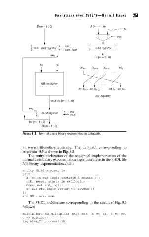
               FIGURE 8.3  Normal basis binary exponentiation datapath.


               at www.arithmetic-circuits.org. The datapath corresponding to
               Algorithm 8.5 is shown in Fig. 8.3.
                  The entity declaration of the sequential implementation of the
               normal basis binary exponentiation algorithm given in the VHDL file
               NB_binary_exponentiation.vhd is

               entity NB_binary_exp is
               port (
                 a, e: in std_logic_vector(M-1 downto 0);
                 clk, reset, start: in std_logic;
                 done: out std_logic;
                 b: out std_logic_vector(M-1 downto 0)
               );
               end NB_binary_exp;

                  The VHDL architecture corresponding to the circuit of Fig. 8.3
               follows:

               multiplier: NB_multiplier port map (a  => bb, b  => cc,
               c => mult_bc);
               register_C: process(clk)
   266   267   268   269   270   271   272   273   274   275   276