
Page 334 - Hardware Implementation of Finite-Field Arithmetic
P. 334
314 App endix A
Recall that in the second case (SRT) the final steps (decoding from
stored-carry form to normal form and correction if the obtained result
is negative) are computed with carry-propagate adders and that the
corresponding delays could be greater than the clock period. As
mentioned in Comment 2.1, some kind of synchronization of the final
operations should be introduced, for example, adding s clock periods
with s such that sT > T .
CLK final steps
A.2.2 Specific Combinational Circuit
Another option is the specific circuit described in Sec. 2.6.2.
A.2.3 FPGA Implementation
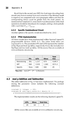
All three circuits have been implemented within Spartan3 (speed-5)
programmable devices (Table A.1). The times (total time) are
expressed in ns. The parameters FFs and LUTs represent the number
of flip-flops and look-up tables, respectively. Every slice includes two
flip-flops and two look-up tables. All the source files are available at
www.arithmetic-circuits.org.
Total
FFs LUTs Slices time
Nonrestoring 391 1,157 679 4166.4
SRT 583 2,525 1,365 1574.4
Specific None 648 642 45
TABLE A.1 mod (2 192 − 2 64 − 1) Reducers
A.3 mod p Addition and Subtraction
The adder-subtractor of Fig. 3.3 has been implemented. The package
storing the parameter values includes the following constant
definitions:
constant K: integer := 192;
constant M: std_logic_vector(k-1 downto 0) :=
X”fffffffffffffffffffffffffffffffeffffffffffffffff”;
The implementation results are the following (Spartan3, speed-5):
LUTs Slices Total time
25 13 9
All the source files are available at www.arithmetic-circuits.org.