
Page 330 - Hardware Implementation of Finite-Field Arithmetic
P. 330
310 Cha pte r T e n
bEqual0 <= ‘1’ when b = 0 else ‘0’;
a1xorb0 <= a(1) xor b(0);
The complete model additionally includes a control unit.
Comment 10.4 In order to minimize the computation time, the circuit
should be slightly modified. The part of the circuit that computes
next_a and next_b is the critical path that defines the clock period. If
ripple-carry adders are used, the minimum clock period should be of
the order of mT . Nevertheless, the updating of a and b is performed
FA
in parallel with the updating of x and y , and in many cases the
Q Q
computation of x and y is executed by the point-addition component.
Q Q
In this case, it is not necessary to compute next_a and next_b in one cycle.
The updating of a and b (ce_ab = 1) can be done at the same time as the
updating of x and y (ce_Q = 1). The problem arises when the updating
Q Q
of x and y is done in one cycle, that is, when a is even (x and y do
Q Q Q Q
not change) and when Q = ∞ (x = x and y = y or x + y ). A simple
Q P Q P P P
solution consists of adding additional no-operation states to the control
unit in such a way that every time a is even or P = ∞, the updating of
a and b (ce_ab = 1) is delayed a number s of cycles, sT being greater
CLK
than the computation time of next_a and next_b.
10.6 FPGA Implementation
The complete point multiplication circuit of Fig. 10.2 has been
implemented within a Spartan3 (speed-5) programmable device with
P defined by the following hexadecimal coordinates:
x = 2fe13c0537bbc11acaa07d793de4e6d5e5c94eee8
P
y = 289070fb05d38ff58321f2e800536d538ccdaa3d9
P
The order of P is equal to
n = 4000000000000000000020108a2e0cc0d99f8a5ef
The circuit computes kP for any k belonging to the interval 0 < k < n.
Because the number of cycles depends on the value of k, average
values have been computed.
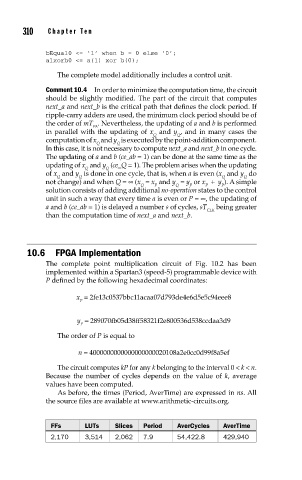
As before, the times (Period, AverTime) are expressed in ns. All
the source files are available at www.arithmetic-circuits.org.
FFs LUTs Slices Period AverCycles AverTime
2,170 3,514 2,062 7.9 54,422.8 429,940