
Page 91 - Hardware Implementation of Finite-Field Arithmetic
P. 91
74 Cha pte r T h ree
p s (k + 1) p c (k + 1) p s (k) p c (k) p s (k – 1) p c (k – 1) y (k – 1) p s (1) p c (1) y (1) p s (0) y (0)
HA FA FA ... FA HA
0
s s (k + 1) s c (k + 1) s s (k) s c (k) s s (k – 1) s c (k – 1) s s (1) s c (1) s s (0) s c (0)
w (k + 1..k – 1) w (k + 1..k – 1)
s
2p (k..0) s s 2p (k..0) s c
s c c
0 –m m
0 1 0 1 step_type 00 01 10 3-bit adder
t
two 3-input
w w
s c u Boolean
functions
w s (k + 1) w c (k + 1) u (k + 1) w s (k) w c (k) u (k) w s (k – 1) w c (k – 1) u (k – 1) w s (1) quotient u (1) w s (0) w c (0) u (0)
w c (1)
FA FA FA ... FA FA
0
ce condition
(2k + 1)-bit register
clear load
p s (k + 1) p c (k + 1) p s (k) p c (k) p s (k – 1) p c (k – 1) p s (1) p c (1) p s (0) p c (0)
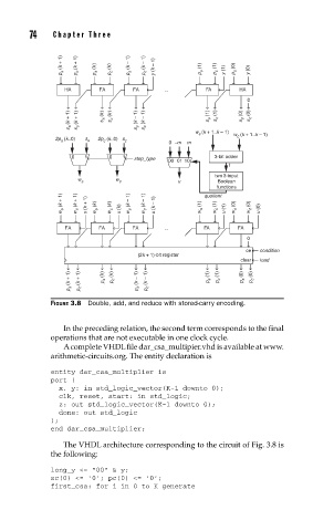
FIGURE 3.8 Double, add, and reduce with stored-carry encoding.
In the preceding relation, the second term corresponds to the final
operations that are not executable in one clock cycle.
A complete VHDL file dar_csa_multipier.vhd is available at www.
arithmetic-circuits.org. The entity declaration is
entity dar_csa_multiplier is
port (
x, y: in std_logic_vector(K-1 downto 0);
clk, reset, start: in std_logic;
z: out std_logic_vector(K-1 downto 0);
done: out std_logic
);
end dar_csa_multiplier;
The VHDL architecture corresponding to the circuit of Fig. 3.8 is
the following:
long_y <= “00” & y;
sc(0) <= ‘0’; pc(0) <= ‘0’;
first_csa: for i in 0 to K generate