
Page 154 - High Power Laser Handbook
P. 154
122 Diode Lasers Semiconductor Laser Diodes 123
Laser diode
Emission
Lens
Attach
Submount
Fiber output
Fiber mount
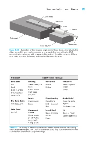
Figure 5.20 Illustration of fiber-coupled single-emitter laser diode. Alternatively, the
chisel (or wedge) lens may be replaced by a separate fast-axis collimator (FAC)
mounted to the submount with a separate fiber output. The white stripe is ~100 mm
wide lasing aperture that nearly matches the fiber core diameter.
Submount Fiber-Coupled Package
Heat Sink Housing Wire Bond Snout Seal
AlN Steel frame, Cu Au ball Metal or glass
BeO base Ribbon solder
CuW (15/85) Kovar frame, Epoxy
CTE-matched CuW base
composite (20/80)
Leads Fiber Coupling Strain Relief
Die-Bond Solder Cu-core alloy Chisel lens Epoxy (at strip
AuSn (80/20) Kovar FAC + cleaved region)
fiber Urethane boot
Wire Bond Component Lens Attach Lid
Au ball Attach Glass or metal Steel or Kovar
Metal solder solder Getter (optional)
(< MP AuSn) Epoxy
(e.g., SAC,
SnAg, BiSn)
Table 5.3 Summary of Key Components and Assembly Methods for Fabricating
Fiber-Coupled Packages. The Chip-On-Submount (Left) May Stand Alone or Become
a Component of the Fiber-Coupled Package