
Page 235 - High Power Laser Handbook
P. 235
204 So l i d - S t at e La s e r s Zigzag Slab Lasers 205
Near field Far field-unphased Far field-phased
1
0.8
0.6
0.4
0.2
0
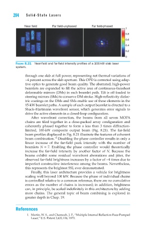
Figure 8.21 Near-field and far-field intensity profiles of a 100-kW slab laser
system.
through one slab at full power, representing net thermal variations of
~4 percent across the slab aperture. This OPD is corrected using adap-
tive optics to generate good beam quality. The aberrated, high-power
beamlets are expanded to fill the active area of continuous-facesheet
deformable mirrors (DMs) in each beamlet path. Tilt is off-loaded to
steering mirrors (SMs) to conserve DM stroke. High-reflectivity dielec-
tric coatings on the DMs and SMs enable use of these elements in the
15-kW beamlet paths. A sample of each output beamlet is directed to a
Shack–Hartmann wavefront sensor, which generates error signals to
drive the active elements in a closed-loop configuration.
After wavefront correction, the beams from all seven MOPA
chains are tiled together in a close-packed array configuration and
coherently phased together to form a less than 3 times diffraction-
limited, 100-kW composite output beam (Fig. 8.21). The far-field
beam profiles displayed in Fig. 8.21 illustrate the features of coherent
14
beam combination. Disabling the phase controller results in only a
linear increase of the far-field peak intensity with the number of
beamlets N = 7. Enabling the phase controller would theoretically
increase the far-field intensity by another factor of N. Because the
beams exhibit some residual wavefront aberrations and jitter, the
observed far-field brightness increases by a factor of ~4 times due to
imperfect constructive interference among the beams. Nevertheless,
this represents the brightest SSL ever demonstrated.
Finally, this laser architecture provides a vehicle for brightness
scaling well beyond 100 kW. Because the phase of individual chains
is controlled relative to a common reference, there are no cumulative
errors as the number of chains is increased; in addition, brightness
can, in principle, be scaled indefinitely in this architecture by adding
more chains. The general topic of beam combining is explored in
greater depth in Chap. 19.
References
1. Martin, W. S., and Chernoch, J. P., “Multiple Internal Reflection Face-Pumped
Laser,” U.S. Patent 3,633,126; 1972.