
Page 233 - High Power Laser Handbook
P. 233
202 So l i d - S t at e La s e r s Zigzag Slab Lasers 203
Slab Diode
cassette arrays
4000
3500
Extracted power (W) 2500
3000
2000
1500
1000
500
0
0 10 20 30 40 50 60 70 80
Diode power (W/bar)
(a) (b)
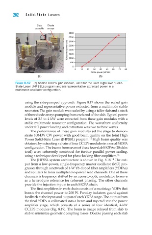
Figure 8.17 (a) Scaled CCEPS gain module, used for the Joint High-Power Solid-
State Laser (JHPSSL) program and (b) representative extracted power in a
multimode oscillator configuration.
using the side-pumped approach. Figure 8.17 shows the scaled gain
module and representative power extracted from a multimode stable
resonator. The gain module was scaled by using a taller slab and a stack
of three diode arrays pumping from each end of the slab. Typical power
levels of 3.5 to 4 kW were extracted from these gain modules with a
stable multimode resonator configuration. The wavefront uniformity
under full power loading and extraction was two to three waves.
The performance of these gain modules set the stage to demon-
strate 100-kW CW power with good beam quality on the Joint High
Power Solid-State Laser (JHPSSL) program. High beam quality was
12
obtained by extracting a chain of four CCEPS modules in a serial MOPA
configuration. The beams from seven of these four-slab MOPAs (28 slabs
total) were coherently combined for further parallel power scaling,
using a technique developed for phase locking fiber amplifiers. 13
14
The JHPSSL system architecture is shown in Fig. 8.18. The out-
put from a low-power, single-frequency master oscillator (MO) pro-
gresses through a network of 1-W Yb-doped fiber amplifiers (YDFAs)
and splitters to form multiple low-power seed channels. One of these
channels is frequency shifted by an acousto-optic modulator to serve
as a heterodyne reference for coherent phasing. The other channels
provide the injection inputs to each MOPA chain.
The first amplifiers in each chain consist of a mutistage YDFA that
boosts the channel power to 200 W. Faraday isolators guard against
feedback at the input and output of each YDFA stage. The output from
the final YDFA is collimated into a beam and injected into the power
amplifier stage, which consists of a series of four identical, 4-kW
CCEPS modules (Fig. 8.19). The beam is image relayed from slab to
slab to minimize geometric coupling losses. Double passing each slab