
Page 263 - High Power Laser Handbook
P. 263
232 So l i d - S t at e La s e r s Thin-Disc Lasers 233
temperature of 15°C were used. We can also calculate an ultimate
limit of the absorbed pump power density, because we must avoid boiling
of the cooling fluid. With 300 W/mm² absorbed pump power density the
resulting temperature at the back side of the heat sink would be 96°C.
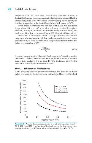
From these calculations we can also derive that the maximum
temperature difference DT in the disc will keep constant for a given
material, as long as the ratio of absorbed pump power density and
thickness of the disc is constant. Figure 10.3 illustrates this relation.
It is useful to introduce a thermal load parameter C which is the
maximum allowed product of disc thickness and (absorbed) pump
power density to keep the maximum temperature rise inside the disc
below a given value of DT:
2Dη
T
C = heat (10.6)
l th
A similar parameter, the “thermal shock parameter”, is often used in
the context of slab lasers or active mirror lasers without additional
supporting structures. It is motivated by the limitations given by the
maximum thermally induced tensile stress.
10.5.2 Influence of Fluorescence
Up to now, only the heat generated inside the disc from the quantum
defect was used for the temperature estimations. However, if we look
200 ∆T = 50 K
Absorbed pump power density (W/mm 2 ) 140 ∆T = 150 K
180
160
∆T = 100 K
120
100
80
60
40
20
0
0.0 0.1 0.2 0.3 0.4
Disc thickness h (mm)
Figure 10.3 Absorbed pump power density to reach a temperature rise of
50 K, 100 K and 150 K as function of the thickness of the disc (assuming a
–1
–1
heat generation η = 8.7% and a thermal conductivity l = W m K ).
heat th