
Page 265 - High Power Laser Handbook
P. 265
234 So l i d - S t at e La s e r s Thin-Disc Lasers 235
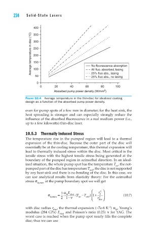
400
Average temperature in disc (°C) 300
350
250
200
150
100
All fluo. absorbed, lasing
25% fluo abs., lasing
50 No fluorescence absorption
25% fluo abs., no lasing
0
0 20 40 60 80 100
2
Absorbed pump power density (W/mm )
Figure 10.4 Average temperature in the thin-disc for idealized coating
design as a function of the absorbed pump power density.
even for pump spots of a few mm in diameter; for the heat sink, the
heat spreading is stronger and can especially strongly reduce the
influence of the absorbed fluorescence in a real medium power (i.e.,
up to a few kilowatts) thin-disc laser.
10.5.3 Thermally Induced Stress
The temperature rise in the pumped region will lead to a thermal
expansion of the thin-disc. Because the outer part of the disc will
essentially be at the cooling temperature, this thermal expansion will
lead to thermally induced stress within the disc. Most critical is the
tensile stress with the highest tensile stress being generated at the
boundary of the pumped region in azimuthal direction. In an ideal-
ized situation, the whole pump spot has the temperature T , the not-
av
pumped part of the disc has temperature T cool , the disc is not supported
by any heat sink and there is no bending of the disc. In this case, we
can use analytical results from elasticity theory: For the azimuthal
stress σ at the pump boundary spot we will get
f,max
1 α E r 2
σ = th elast (T − ) 1 +T p (10.7)
2
f,max 21 − ν av cool r disc
–1
with disc radius r , the thermal expansion (~7e-6 K ) α , Young’s
th
disc
modulus (284 GPa) E elast and Poisson’s ratio (0.25) ν for YAG. The
worst case is reached when the pump spot nearly fills the complete
disc; thus we can use