
Page 267 - High Power Laser Handbook
P. 267
236 So l i d - S t at e La s e r s Thin-Disc Lasers 237
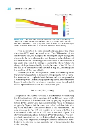
First principal stress [MPa]
50
0
−50
−100
−150
−200
−250
Figure 10.6 Calculated first principal stress and deformation (scaled by
100) for a Yb:YAG thin-disc of thickness 150 µm, mounted on a CuW heat
sink with thickness of 1 mm, pump spot radius 7.5 mm, and heat source per
area 5.4 W/mm², equivalent to 60 W/mm² absorbed power density.
From the results of the finite element software, the optical phase
distortion (OPD) Φ()r can be calculated. The OPD consists of two
contributions: first, the change of the optical path length through the
disc due to the thermal expansion and thermally induced change of
the refractive index (what is typically considered as thermal lens for
rod lasers) and second, the change of shape of the whole system. The
change of shape is described by the displacement of the HR face of
the disc. Both contributions are depicted in Fig. 10.7, including also
the resulting OPD as sum of both.
The main part of the OPD is parabolic, caused by the bending due to
the temperature gradients in the system. This parabolic part is equiva-
lent to a curvature or a spherical contribution which can be expressed as
a refractive power. The remaining aspherical part will cause diffraction
losses. To determine the curvature or refractive power, the calculated
OPD is separated into spherical and an aspherical part:
Φ r / ( R + D() r= −2π Φ() (10.9)
l
)
2
r
L
The optimum value of the curvature R is determined by calculating
L
the diffraction losses of the remaining DΦ for different values of R .
L
This calculation of diffraction loss is done by applying the phase dis-
tortion DΦ to a plane wave (fundamental mode with a mode radius
of typically 70 percent of the pump spot radius) and then determin-
ing which amount of the distorted mode is still fundamental. The
data presented in Fig. 10.7 will result in a curvature of 2.98 m if a
fundamental mode radius of 5.25 mm is assumed. Figure 10.8
shows the remaining phase distortion DΦ of this analysis. Two non-
parabolic contributions can be distinguished: a step-like structure
(~500 nm) at the edge of the pump spot due to the temperature distri-
bution in the disc and the non-parabolic part of the deformation due
to the clamping.