
Page 271 - High Power Laser Handbook
P. 271
240 So l i d - S t at e La s e r s Thin-Disc Lasers 241
0.2
0.0
Dioptric power (m −1 ) −0.2 Classical design,
−0.4
soldered on CuW
−0.6
Composite disk,
directly cooled
−0.8
0 1 2 3 4 5 6 7 8 9
2
Pump power density (kW/cm )
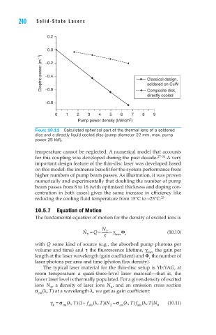
Figure 10.11 Calculated spherical part of the thermal lens of a soldered
disc and a directly liquid cooled disc (pump diameter 22 mm, max. pump
power 25 kW).
temperature cannot be neglected. A numerical model that accounts
for this coupling was developed during the past decade. 27–31 A very
important design feature of the thin-disc laser was developed based
on this model: the immense benefit for the system performance from
higher numbers of pump beam passes. As illustration, it was proven
numerically and experimentally that doubling the number of pump
beam passes from 8 to 16 (with optimized thickness and doping con-
centration in both cases) gives the same increase in efficiency like
reducing the cooling fluid temperature from 15°C to –25°C. 29
10.5.7 Equation of Motion
The fundamental equation of motion for the density of excited ions is
N = & 2 Q − N τ 2 − γ laser Φ r (10.10)
with Q some kind of source (e.g., the absorbed pump photons per
volume and time) and τ the fluorescence lifetime, γ laser the gain per
length at the laser wavelength (gain coefficient) and Φ the number of
r
laser photons per area and time (photon flux density).
The typical laser material for the thin-disc setup is Yb:YAG, at
room temperature a quasi-three-level laser material—that is, the
lower laser level is thermally populated. For a given density of excited
ions N , a density of laser ions N , and an emission cross section
0
2
σ l (, T) at a wavelength l, we get as gain coefficient:
em
l
γ l σ = em (, + f (, TN 2 σ − em l (, Tf ( l T)N (10.11)
l T)(1
)
))
)
,
0
abs
abs