
Page 288 - High Power Laser Handbook
P. 288
256 So l i d - S t at e La s e r s Thin-Disc Lasers 257
Yb:YAG
thin disc
Polarizer λ/4 Pockels cell
HR 1030 nm
HR 515 nm
SHG crystal
HR 1030 nm
HT 515 nm
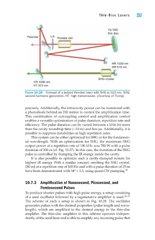
Figure 10.26 Concept of a pulsed thin-disc laser with SHG at 515 nm. SHG:
second harmonic generation, HT: high transmission. (Courtesy of Trump)
precisely. Additionally, the intracavity power can be monitored with
a photodiode behind an HR mirror to control the amplification time.
This combination of outcoupling control and amplification control
enables a versatile optimization of pulse duration, repetition rate and
efficiency. The pulse duration can be varied between a little bit more
than the cavity roundtrip time (~10 ns) and few ms. Additionally, it is
possible to suppress instabilities at high repetition rates.
This system can be either optimized for SHG or for the fundamen-
tal wavelength. With an optimization for SHG, the maximum SHG
output power at a repetition rate of 100 kHz was 700 W with a pulse
duration of 300 ns (cf. Fig. 10.27). In this case, the duration of the SHG
pulse is controlled by dumping the IR energy inside the cavity.
It is also possible to optimize such a cavity-dumped system for
highest IR energy. With a similar concept, omitting the SHG crystal,
280 mJ at a repetition rate of 100 Hz and with a pulse duration of 25 ns
have been demonstrated with M² < 1.3, using quasi-CW pumping. 58
10.7.3 Amplification of Nanosecond, Picosecond, and
Femtosecond Pulses
To produce shorter pulses with high pulse energy, a setup consisting
of a seed oscillator followed by a regenerative amplifier is used. 58–61
The scheme of such a setup is shown in Fig. 10.28. The oscillator
generates pulses with the desired properties (pulse length and wave-
length), which are amplified to the desired energy in the thin-disc
amplifier. The thin-disc amplifier in this scheme operates indepen-
dently of the seed laser and is able to amplify any incoming pulse that