
Page 289 - High Power Laser Handbook
P. 289
258 So l i d - S t at e La s e r s Thin-Disc Lasers 259
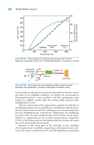
Laser power (W) Opt.-opt. efficiency (%) (pump power to green)
Laser power Efficiency
Pump power (W)
Figure 10.27 Output power of a cavity-dumped system with internal
frequency conversion at 515 nm in multimode operation. (Courtesy of Trump)
Separation HR
Pockels cell
input/output
Polarizer
Laser disk
HR
Figure 10.28 Schematic setup of an oscillator-amplifier system for pulse
generation and amplification. (Courtesy of Dausinger und Giesen Gmbh)
has the right wavelength and a pulse duration shorter than the round-
trip time of the amplifier resonator. To amplify the picosecond or
femtosecond pulses, a seed oscillator with the appropriate pulse
length (i.e., slightly shorter than the desired pulse duration after
amplification) is used.
The key components of the regenerative amplifier are the disc as
amplifying medium and the polarizer in combination with the Pock-
els cell as polarization switch for switching in and out the seed pulses
and the amplified pulses, respectively. Additionally, for amplifying
fs-pulses, Gires-Tournois interferometer (GTI) mirrors can be imple-
mented to compensate for the positive group-velocity dispersion
(GVD) of the Pockels cell and the optical elements during one round
trip of the pulse inside the resonator.
Because of the small gain of the thin-disc in the amplifier
(10–40 percent per roundtrip, depending on the operational condi-
tions), the pulses need between 50 and 200 amplifying roundtrips