
Page 471 - High Power Laser Handbook
P. 471
438 Fi b er L a s er s Intr oduction to Optical Fiber Lasers 439
(a) (b)
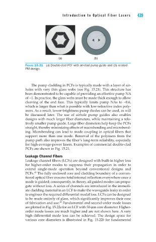
Figure 15.21 (a) Double-clad PCF with air-clad pump guide and (b) related
PM design.
The pump cladding in PCFs is typically made with a layer of air-
holes with very thin glass webs (see Fig. 15.21). This structure has
been demonstrated to be capable of providing an effective pump NA
of ~1. In practice, the glass webs must be made thick enough to allow
cleaving of the end face. This typically limits pump NAs to ~0.6,
which is larger than what is possible with low-refractive index poly-
mers. As a result, lower-brightness pump diodes can be used, as will
be discussed later. The use of airhole pump guides also enables
designs with much larger fiber diameters, while maintaining a rela-
tively smaller pump guide. Large fiber diameters help keep the PCFs
straight, thereby minimizing effects of macrobending and microbend-
ing. Microbending can lead to mode coupling in optical fibers that
support more than one mode. Removal of the polymers from the
pump path also improves the fiber’s long-term reliability, especially
for high-average-power lasers. Examples of commercial double-clad
PCFs are shown in Fig. 15.21.
Leakage Channel Fibers
Leakage channel fibers (LCFs) are designed with built-in higher loss
for higher-order modes to suppress their propagation in order to
extend single-mode operation beyond conventional designs and
40
PCFs. The fully enclosed core and cladding boundary of a conven-
tional optical fiber ensures total internal reflection everywhere once a
mode is guided; consequently, in theory, all guided modes can propa-
gate without loss. A series of channels are introduced in the immedi-
ate cladding material in an LCF to make the waveguide leaky in order
to engineer the required differential modal loss. LCFs can be designed
to be made entirely of glass, which significantly improves their ease
of fabrication and use. Fundamental and second-order mode losses
41
are plotted in Fig. 15.22a for an LCF with 50-µm core diameter. Higher-
order mode losses are much higher and are not shown here. A very
high differential mode loss can be achieved. The design space for
various core diameters is illustrated in Fig. 15.22b for fundamental