
Page 473 - High Power Laser Handbook
P. 473
440 Fi b er L a s er s Intr oduction to Optical Fiber Lasers 441
0.35
0.30
Critical bend radius (m) 0.25
0.20
0.15
1 dB/m
2 dB/m
0.10
35 60 85 110
Core diameter (µm)
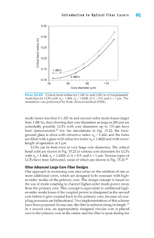
Figure 15.23 Critical bend radius for 1 dB/m and 2 dB/m of fundamental
mode loss for LCFs with n = 1.444, n = 1.4428, d/Λ = 0.9, and λ = 1 µm. The
B
F
simulation was performed by finite element method (FEM).
mode losses less than 0.1 dB/m and second-order mode losses larger
than 1 dB/m, thus showing that core diameters as large as 200 µm are
potentially possible. LCFs with core diameters up to 170 µm have
42
been demonstrated. For the simulations in Fig. 15.22, the back-
ground glass is silica with refractive index n = 1.444, and the holes
B
are filled with a glass with refractive index n = 1.4428 and with wave-
F
length of operation at 1 µm.
LCFs can be bent even at very large core diameters. The critical
bend radii are shown in Fig. 15.23 at various core diameters for LCFs
with n = 1.444, n = 1.4428, d/Λ = 0.9, and λ = 1 µm. Various types of
F
B
LCFs have been fabricated, some of which are shown in Fig. 15.24. 43
Other Advanced Large-Core Fiber Designs
One approach to increasing core area relies on the addition of one or
more additional cores, which are designed to be resonant with high-
er-order modes of the primary core. The design concept is based on
the use of mode coupling to channel higher-order mode power away
from the primary core. This concept is equivalent to additional high-
er-order mode losses if the coupled power is dissipated in the second
core before it gets coupled back to the primary core, because all cou-
pling processes are bidirectional. Two implementations of this scheme
44
have been proposed. In one case, the fiber is uniform along its length.
In a second case, an appropriately designed circular core is placed
next to the primary core at the center, and the fiber is spun during the