Page 484 - High Power Laser Handbook
P. 484
452    Fi b er   L a s er s                                                                                      Intr oduction to Optical Fiber Lasers    453


                          Pump                                       Pump
                              Pump                               Pump
                                  Pump                       Pump

                      Pump                                                Output


                                  Pump                       Pump
                              Pump                               Pump
                          Pump                                       Pump


                 Pump core              Pump
                                                                         Output
                             HR   Doped core                       OC
                     Pump
                   cladding
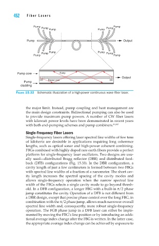
                 Figure 15.32  Schematic illustration of a high-power continuous wave fiber laser.


                      the major limit. Instead, pump coupling and heat management are
                      the main design constraints. Bidirectional pumping can also be used
                      to provide maximum pump powers. A number of CW fiber lasers
                      with kilowatt power levels have been demonstrated in recent years
                      with both end-pumping schemes and pump combiners. 61,62
                      Single-Frequency Fiber Lasers
                      Single-frequency lasers offering laser spectral line widths of few tens
                      of  kilohertz  are  desirable  in  applications  requiring  long  coherence
                      lengths, such as optical sonar and high-power coherent combining.
                      FBGs combined with highly doped rare earth fibers provide a perfect
                      platform for single-frequency laser oscillators. Two designs are usu-
                      ally  used—distributed  Bragg  reflector  (DBR)  and  distributed  feed-
                      back (DFB) configurations (Fig. 15.33). In the DBR configuration, a
                      cavity length of just a few centimeters is formed between two FBGs
                      with spectral line widths of a fraction of a nanometer. The short cav-
                      ity  length  increases  the  spectral  spacing  of  the  cavity  modes  and
                      allows  single-frequency  operation  when  the  narrow  spectral  line
                      width of the FBGs selects a single cavity mode to go beyond thresh-
                      old. In a DFB configuration, a longer FBG with a built-in π/2 phase
                      jump constitutes the cavity. Operation of a DFB is not different from
                      a DBR design, except that precise phase control over the long FBG, in
                      combination with the π/2 phase jump, allows much narrower overall
                      spectral line width and, consequently, more robust single-frequency
                      operation. The FGB phase jump in a DFB laser can either be imple-
                      mented by moving the FBG’s line position or by introducing an addi-
                      tional average index change after the FBG is written. In the latter case,
                      the appropriate average index change can be achieved by exposure to

