Page 489 - High Power Laser Handbook
P. 489
456   Fi b er   L a s er s            Intr oduction to Optical Fiber Lasers    457


                         In Fig. 15.36, a semiconductor saturable absorber is used as a pas-
                      sive amplitude modulator. The use of PM fiber throughout the cavity
                      allows  for  environmentally  stable  single-polarization  operation.  A
                      chirped  fiber  grating  is  used  for  dispersion  compensation,  which
                      allows  for  a  very  compact  system  construction.  With  the  attached
                      fiber amplifier, pulse energies up to 10 nJ can be generated, and the
                      pulse widths can be as short as 100 fs. As with actively mode-locked
                      lasers, the system from Fig. 15.36 can also produce gaussian-shaped
                      pulses, in which, assuming optimum dispersion compensation, the
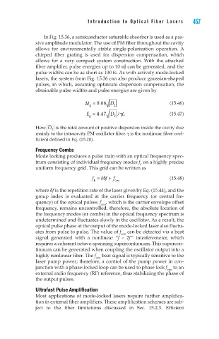
                      obtainable pulse widths and pulse energies are given by

                                         ∆  =t  066  D                    (15.46)
                                               .
                                           g        2
                                                        L
                                          E = 447  D /γ                   (15.47)
                                               .
                                           g        2
                      Here  D  is the total amount of positive dispersion inside the cavity due
                            2
                      mainly to the intracavity PM oscillator fiber. γ is the nonlinear fiber coef-
                      ficient defined in Eq. (15.20).
                      Frequency Combs
                      Mode locking produces a pulse train with an optical frequency spec-
                      trum consisting of individual frequency modes f  on a highly precise
                                                               k
                      uniform frequency grid. This grid can be written as
                                            f =  k f + δ  f               (15.48)
                                             k       ceo
                      where δf is the repetition rate of the laser given by Eq. (15.44), and the
                      group  index  is  evaluated  at  the  carrier  frequency  (or  central  fre-
                      quency) of the optical pulses. f , which is the carrier envelope offset
                                                ceo
                      frequency, remains uncontrolled; therefore, the absolute location of
                      the frequency modes (or combs) in the optical frequency spectrum is
                      undetermined and fluctuates slowly in the oscillator. As a result, the
                      optical pulse phase at the output of the mode-locked laser also fluctu-
                      ates from pulse to pulse. The value of f  can be detected via a beat
                                                       ceo
                      signal  generated  with  a  nonlinear  “f  –  2f ”  interferometer,  which
                      requires a coherent octave-spanning supercontinuum. This supercon-
                      tinuum can be generated when coupling the oscillator output into a
                      highly nonlinear fiber. The f  beat signal is typically sensitive to the
                                             ceo
                      laser pump power; therefore, a control of the pump power in con-
                      junction with a phase-locked loop can be used to phase lock f  to an
                                                                         ceo
                      external radio frequency (RF) reference, thus stabilizing the phase of
                      the output pulses.
                      Ultrafast Pulse Amplification
                      Most applications of mode-locked lasers require further amplifica-
                      tion in external fiber amplifiers. These amplification schemes are sub-
                      ject  to  the  fiber  limitations  discussed  in  Sec.  15.2.3.  Efficient

