
Page 487 - High Power Laser Handbook
P. 487
454 Fi b er L a s er s Intr oduction to Optical Fiber Lasers 455
where k is an integer, c is the velocity of light, n is the phase index at
p
frequency f , and L is the cavity length. To a first order approximation,
k
the cavity mode spacing δf can then be written as
c
δf = (15.44)
nL
g
Note that due to dispersion, the cavity mode spacing is slightly
nonuniform in any cavity that contains an actual physical gain
medium. Therefore the cavity mode spacing is governed by the group
index n rather than by the phase index n .
p
g
In active mode locking, a modulator operating at the cavity
round-trip time is introduced into the cavity. A subsection of the
cavity modes then becomes phase locked through the generation of
side bands from the modulator. Moreover, the applied modulation
pulls the cavity modes into a precisely uniform frequency grid,
leading to the generation of stable pulses at the repetition rate given
by Eq. 15.44.
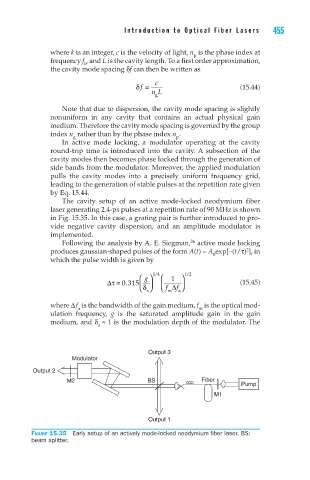
The cavity setup of an active mode-locked neodymium fiber
laser generating 2.4-ps pulses at a repetition rate of 90 MHz is shown
in Fig. 15.35. In this case, a grating pair is further introduced to pro-
vide negative cavity dispersion, and an amplitude modulator is
implemented.
Following the analysis by A. E. Siegman, active mode locking
26
2
produces gaussian-shaped pulses of the form A(t) = A exp[–(t/τ) ], in
0
which the pulse width is given by
/
/
g 14 1 12
τ
.
∆= 0 315 f (15.45)
δ a f m ∆
a
where ∆ f is the bandwidth of the gain medium, f is the optical mod-
m
a
ulation frequency, g is the saturated amplitude gain in the gain
medium, and δ ≈ 1 is the modulation depth of the modulator. The
a
Output 3
Modulator
Output 2
M2 BS Fiber
Pump
M1
Output 1
Figure 15.35 Early setup of an actively mode-locked neodymium fiber laser. BS:
beam splitter.