
Page 505 - High Power Laser Handbook
P. 505
472 Fi b er L a s er s Pulsed Fiber Lasers 473
Here A is beam area and P is peak power. Even in the most extreme
single-mode Yb-doped fibers (e.g., A = ~5000 μm ), corresponding to
2
the LP mode in a ~100-μm core fiber, and for P exceeding P by a
01
c
mere 10 percent, L is already less than 15 mm—that is, it is much
c
shorter than any fiber length of practical usability. In bulk crystals,
however, A can be much larger, and significant energy can be extracted
even in a few centimeter lengths.
So far, the high-peak-power onset of SF in rare-earth-doped, as
well as transport, fibers has proved a rather elusive phenomenon to
conclusively observe. There still exists experimental evidence with
which the theory has not been completely reconciled. One of them
pertains to the SF behavior of high-order fiber modes, which are cal-
culated to exhibit intrinsic P values that are several times higher than
c
LP , but which are then predicted to undergo spatial instabilities
01
during propagation and to incur collapse at about the same power
level of 4 to 5 MW. Further analysis is warranted, as such a descrip-
15
tion does not seem consistent with the reported delivery of greater
than 20 MW peak power pulses with a highly multimode passive
18
fiber. Moreover, alternative analyses have recently been presented
according to which the in-fiber P for LP does depend on mode field
c
01
area, due to the onset of spatial beam filamentation, which is caused
by spatial hole burning in fiber amplifiers. 19
Fiber facets are normally subject to damage at much lower irradi-
ance values than the fiber bulk. However, this difference is largely
extrinsic and ascribed to the fiber facet’s much lower optical quality,
which is due to imperfections left behind by the cleaving and polish-
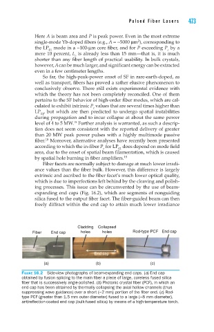
ing processes. This issue can be circumvented by the use of beam-
expanding end caps (Fig. 16.2), which are segments of nonguiding
silica fused to the output fiber facet. The fiber-guided beam can then
freely diffract within the end cap to attain much lower irradiance
Cladding Collapsed
Fiber End cap holes holes Rod-type PCF End cap
End cap
(a) (b) (c)
Figure 16.2 Side-view photographs of beam-expanding end caps. (a) End cap
obtained by fusion splicing to the main fiber a piece of large, coreless fused silica
fiber that is successively angle-polished. (b) Photonic crystal fiber (PCF), in which an
end cap has been obtained by thermally collapsing the axial hollow channels (thus
suppressing wave guidance) over a short (~2 mm) portion of the fiber end. (c) Rod-
type PCF (greater than 1.5 mm outer diameter) fused to a large (~8 mm diameter),
antireflection-coated end cap (bulk-fused silica) by means of a high-temperature torch.