
Page 81 - High Power Laser Handbook
P. 81
50 G a s , C h e m i c a l , a n d F r e e - E l e c t r o n L a s e r s Chemical Lasers 51
HF laser DF laser
10
9
8
V = 3 7
J = 6
8 10
7 9
6 8
V = 2 V = 2
5 7
J = 4 J = 6
8 10
7 9
6 8
V = 1 V = 1
5 7
J = 4 J = 6
8 10
7 9
6 8
V = 0 V = 0
5 7
J = 4 J = 6
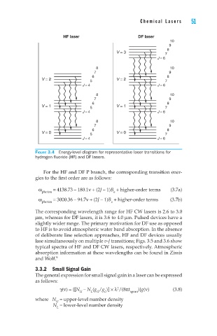
Figure 3.4 Energy-level diagram for representative laser transitions for
hydrogen fluoride (HF) and DF lasers.
For the HF and DF P branch, the corresponding transition ener-
gies to the first order are as follows:
ω = 4138.73 – 180.1ν + (2J – 1)B + higher-order terms (3.7a)
photon e
ω photon = 3000.36 – 94.7ν + (2J – 1)B + higher-order terms (3.7b)
e
The corresponding wavelength range for HF CW lasers is 2.6 to 3.0
µm, whereas for DF lasers, it is 3.6 to 4.0 µm. Pulsed devices have a
slightly wider range. The primary motivation for DF use as opposed
to HF is to avoid atmospheric water band absorption. In the absence
of deliberate line selection approaches, HF and DF devices usually
lase simultaneously on multiple v-J transitions; Figs. 3.5 and 3.6 show
typical spectra of HF and DF CW lasers, respectively. Atmospheric
absorption information at these wavelengths can be found in Zissis
9
and Wolf.
3.3.2 Small Signal Gain
The general expression for small signal gain in a laser can be expressed
as follows:
2
γ(ν) = {[N – N (g /g )] × λ /(8πt spont )}g(ν) (3.8)
L
U
U
L
where N = upper-level number density
U
N = lower-level number density
L