Page 96 - High Power Laser Handbook
P. 96

66     G a s , C h e m i c a l , a n d F r e e - E l e c t r o n L a s e r s                                                          Chemical Lasers     67


                                                  BHP              Optics

                                                           f
                                                         O 2 ( D)
                                       Chlorine  Singlet
                                       (Cl 2  + He)  oxyzen
                     NH 3                       generator
                   Discharges     Main heat                       Iodine
                 directly outside  exchanger                    (I 2  & He) HOT
                    aircraft    ammonia (NH 3 )   BHP+        Gain generator I*, O 2 ( D)
                                                                            f
                   during flight                  H 2 O,
                                                  salt,
                                                  heat
                                                              Diffuser
                 Hydrogen peroxide     Turbo-
                     (H 2 O 2 )  generator  Gas  pump            Hydrogen peroxide
                                                      Optics
                                                                     (H 2 O 2 )
                                                               Pressure recovery system
                                              1.315   m
                                             output beam
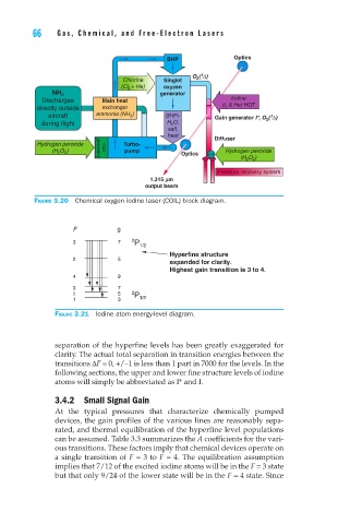
                 Figure 3.20  Chemical oxygen iodine laser (COIL) block diagram.


                           F                        g
                           3          7  2 P 1/2
                                                   Hyperfine structure
                           2          5            expanded for clarity.
                                                   Highest gain transition is 3 to 4.
                           4          9
                           3          7
                           2          5  2 P
                           1          3    3/2
                      Figure 3.21  Iodine atom energy-level diagram.


                      separation of the hyperfine levels has been greatly exaggerated for
                      clarity. The actual total separation in transition energies between the
                      transitions ∆F = 0, +/–1 is less than 1 part in 7000 for the levels. In the
                      following sections, the upper and lower fine structure levels of iodine
                      atoms will simply be abbreviated as I* and I.

                      3.4.2  Small Signal Gain
                      At  the  typical  pressures  that  characterize  chemically  pumped
                      devices, the gain profiles of the various lines are reasonably sepa-
                      rated, and thermal equilibration of the hyperfine level populations
                      can be assumed. Table 3.3 summarizes the A coefficients for the vari-
                      ous transitions. These factors imply that chemical devices operate on
                      a single transition of F = 3 to F = 4. The equilibration assumption
                      implies that 7/12 of the excited iodine atoms will be in the F = 3 state
                      but that only 9/24 of the lower state will be in the F = 4 state. Since
   91   92   93   94   95   96   97   98   99   100   101