
Page 224 - High Temperature Solid Oxide Fuel Cells Fundamentals, Design and Applications
P. 224
Cell and Stack Designs 201
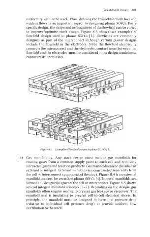
uniformity within the stack. Thus, defining the flowfield for both fuel and
oxidant flows is an important aspect in designing planar SOFCs. For a
specific design, the shape and arrangement of the flowfield can be varied
to improve/optimise stack design. Figure 8.3 shows two examples of
flowfield design used in planar SOFCs [3]. Flowfields are commonly
designed as part of the interconnect although certain planar designs
include the flowfield in the electrodes. Since the flowfield electrically
connects the interconnect and the electrodes, contact area (between the
flowfield and the electrodes) must be considered in the design to minimise
contact resistance losses.
Figure 8.3 Examples offlowfielddesigns inplanar SOFCs [3].
(ii) Gas manifolding. Any stack design must include gas manifolds for
routing gases from a common supply point to each cell and removing
unreacted gases and reaction products. Gas manifolds can be classified as
external or integral. External manifolds are constructed separately from
the cell or interconnect component of the stack. Figure 8.4 is an external
manifold concept for crossflow planar SOFCs [4]. Integral manifolds are
formed and designed as part of the cell or interconnect. Figure 8.5 shows
several integral manifold concepts [S-71. Depending on the design, gas
manifolds often require sealing to prevent gas leakage or crossover. The
manifold seal is insulating to prevent cell-to-cell electrical shorts. In
principle, the manifold must be designed to have low pressure drop
(relative to individual cell pressure drop) to provide uniform flow
distribution to the stack.