
Page 228 - High Temperature Solid Oxide Fuel Cells Fundamentals, Design and Applications
P. 228
Cell and Stack Designs 205
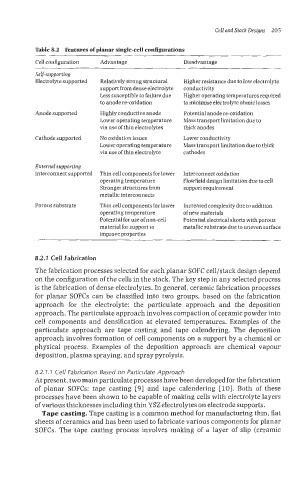
Table 8.2 Features of planar single-cell configurations
Cell configuration Advantage Disadvantage
Self-supporting
Electrolyte supported Relatively strong structural Higher resistance due to low electrolyte
support from dense electrolyte conductivity
Less susceptible to failure due Higher operating temperatures required
to anode re-oxidation to minimise electrolyte ohmic losses
Anode supported Highly conductive anode Potential anode re-oxidation
Lower operating temperature Mass transport limitation due to
via use ofthin electrolytes thick anodes
Cathode supported No oxidation issues Lower conductivity
Lower operating temperature Mass transport limitation due to thick
via use of thin electrolyte cathodes
External supporting
Interconnect supported Thin cell components for lower Interconnect oxidation
operating temperature Flowl?elddesignlimitation due to cell
Stronger structures from support requirement
metallic interconnects
Porous substrate Thin cell components for lower Increased complexity due to addition
operating temperature ofnew materials
Potential for use ofnon-cell Potential electrical shorts with porous
material for support to metallic substrate due to uneven surface
improve properties
8.2.7 Cell Fabrication
The fabrication processes selected for each planar SOFC cell/staclc design depend
on the configuration of the cells in the stack. The key step in any selected process
is the fabrication of dense electrolytes. In general, ceramic fabrication processes
for planar SOPCs can be classified into two groups, based on the fabrication
approach for the electrolyte: the particulate approach and the deposition
approach. The particulate approach involves compaction of ceramic powder into
cell components and densification at elevated temperatures. Examples of the
particulate approach are tape casting and tape calendering. The deposition
approach involves formation of cell components on a support by a chemical or
physical process. Examples of the deposition approach are chemical vapour
deposition, plasma spraying, and spray pyrolysis.
8.2.7.7 Cell Fabrication Based on Particulate Approach
At present, two main particulate processes have been developed for the fabrication
of planar SOFCs: tape casting [9] and tape calendering [lo]. Both of these
processes have been shown to be capable of making cells with electrolyte layers
of various thicknesses including thin YSZ electrolytes on electrode supports.
Tape casting. Tape casting is a common method for manufacturing thin, flat
sheets of ceramics and has been used to fabricate various components for planar
SOFCs. The tape casting process involves malting of a layer of slip (ceramic