
Page 233 - High Temperature Solid Oxide Fuel Cells Fundamentals, Design and Applications
P. 233
2 10 High Temperature Solid Oxide Fuel Cells: Fundamentals, Design and Applications
8.3 Tubular SOFC Design
Two general types of tubular cells are currently being pursued, cells with a large
diameter (> 15 mm), and microtubular cells with a very small diameter
( < 5 mm); the microtubular cells are discussed in Section 8.4.
In the most common tubular design, pioneered by Westinghouse Electric
Corporation (now Siemens Westinghouse Power Corporation), the cell
components are deposited in the form of thin layers on a cylindrical tube [25]. In
the early designs, this tube was made of calcia-stabilised zirconia: this porous
support tube (PST) acted both as a structural member onto which the active cell
components were fabricated and as a functional member to allow the passage of
air to the cathode during cell operation. This porous support tube was fabricated
by extrusion followed by sintering at an elevated temperature. Although
sufficiently porous, this tube presented an inherent impedance to air flow toward
the cathode. Inorder to reduce suchimpedance to air flow, the wall thickness ofthe
porous support tube was first decreased from 2 mm (thick-wall PST) to 1.2 mm
(thin-wall PST), and then the porous support tube was completely eliminated and
replaced by a doped LaMn03 tube (air electrode-supported cell): this tube serves as
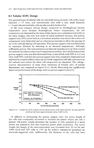
the cathode onto which the other cell components are deposited. The voltage-
current characteristics of these three variations of tubular cells, of similar
dimensions, are compared in Figure 8.12, clearly illustrating the significantly
";
improved performance of the design with no porous support tube [25].
0.8
0.7 -
-
0.6
0.5 -
(85Oh Utilization)
-
0.4 Oxidant: Air (4 Stolchs) nick-wall PST cell
I
0.3
0 100 200 300 400 500 600 700
Current Density (m~cm2)
Figure 8.12 Comparison of the voltage-current characteristics of the thick-wall PST, the thin-waIZ PST,
and the air electrode-supported tubular cellsat 1000°C [25].
In addition to eliminating the porous support tube, the active length of
the cells was continually increased to increase the power output per cell: a
greater cell power output decreases the number of cells required in a given
power size generator and thus improves power plant economics. The active
Iength (the length of the interconnection) was increased from 30 cm for pre-
1986 thick-wall PST cells to 150 cm for today's commercial prototype air
electrode-supported cells. Additionally, the diameter of the cells has been