
Page 237 - High Temperature Solid Oxide Fuel Cells Fundamentals, Design and Applications
P. 237
2 14 High Temperature Solid Oxide Fuel Cells: Fundamentals, Design and Applications
The tubular SOFCs have also shown the ability to be thermally cycled to room
temperature from 1000°C over 100 times without any mechanical damage or
electrical performance loss. This ability to sustain thermal cycles is essential for
any SOFC generator to be commercially viable.
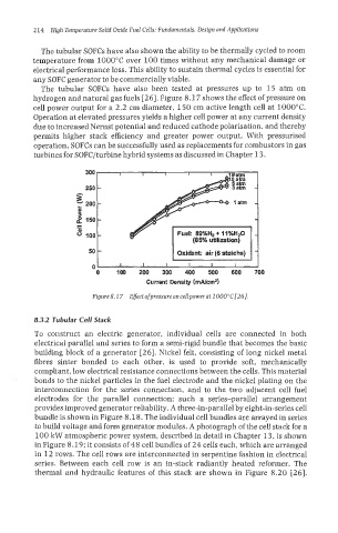
The tubular SOFCs have also been tested at pressures up to 15 atm on
hydrogen and natural gas fuels [26]. Figure 8.1 7 shows the effect of pressure on
cell power output for a 2.2 cm diameter, 150 cm active length cell at 1000°C.
Operation at elevated pressures yields a higher cell power at any current density
due to increased Nernst potential and reduced cathode polarisation, and thereby
permits higher stack efficiency and greater power output. With pressurised
operation, SOFCs can be successfully used as replacements for combustors in gas
turbines for SOFC/turbine hybrid systems as discussed in Chapter 13.
t Oxidant: air (6 stoichs)
0
0 100 200 300 400 500 600 700
Current Density (Wcrn2)
Figure 8.1 7 Effect ofpressureoncellpowerat lOOPC[26].
8.3.2 Tubular Cell Stack
To construct an electric generator, individual cells are connected in both
eIectrica1 parallel and series to form a semi-rigid bundle that becomes the basic
building block of a generator [26]. Nickel felt, consisting of long nickel metal
fibres sinter bonded to each other, is used to provide soft, mechanically
compliant, low electrical resistance connections between the cells. This material
bonds to the nickel particles in the fuel electrode and the nickel plating on the
interconnection for the series connection, and to the two adjacent cell fuel
electrodes for the parallel connection: such a series-parallel arrangement
provides improved generator reliability. A three-in-parallel by eight-in-series cell
bundle is shown in Figure 8.18. The individual cell bundles are arrayed in series
to build voltage and form generator modules. A photograph of the cell stack for a
100 kW atmospheric power system, described in detail in Chapter 13, is shown
in Figure 8.19; it consists of 48 cell bundIes of 24 cells each, which are arranged
in 12 rows. The cell rows are interconnected in serpentine fashion in electrical
series. Between each cell row is an in-stack radiantly heated reformer. The
thermal and hydraulic features of this stack are shown in Figure 8.20 [26].