
Page 239 - High Temperature Solid Oxide Fuel Cells Fundamentals, Design and Applications
P. 239
2 16 High Temperature Solid Oxide Fuel Cells: Fundamentals. Design and Applications
primary fluid is used to extract a portion of the spent fuel and mix it with fresh
fuel before the mixture is introduced into an adiabatic pre-reformer where the
higher hydrocarbons are reformed. From the pre-reformer, the predominantly
methane stream is routed to the top of the in-stack reformers. The mixture flows
downward through catalyst material before exiting within the fuel plenum at the
bottom of the stack. The completely reformed fuel flows upward within the stack
along the exterior of cells where it is electrochemically oxidised. The stack
exhaust gas departs at the combustion zone temperature, approximately 8 50°C.
The stack is cooled with process air which enters the stack at approximately
600°C. The thermally and hydraulically integrated reformer requires no
external source of water during normal operation.
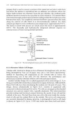
Air
Air Plenum
Combustion Plenum
Depleted Fuel Plenum
Thermocouple
Internal Reformation Zone
PreReformer
hermocouple, Pressure Transducer
Desulfurized PNG
Figure8.20 Thermalandhydraulicfeaturesofthe 100 kWSOFCstack[26].
8.3.3 Alternative Tubular Cell Designs
Tubular cells, identical in design to that of Siemens Westinghouse cells, are also
being developed by Toto Ltd of Japan: they use a ‘wet slurry dip/sintering’
method for depositing cell components on the cathode tube to reduce the
manufacturing cost of the cells [30-341. However, the performance and
performance stability with time of these cells still need improvement.
Another tubular design, the so-called segmented cell-in-series design [2, 31, is
being pursued by Mitsubishi Heavy Industries in Japan. In Europe, ABB and Rolls
Royce Fuel Cells have been developing this system over the past 20 years. This
design, shown schematically in Figure 8.21, consists of segmented cells
connected in electrical and gas flow series. The cells are arranged as thin banded
structure on a porous support tube, typically aluminate. The interconnection
provides sealing (and electrical contact) between the anode of one cell and the
cathode of the next. The fuel flows from one cell to the next inside the tubular
stack of cells and the oxidant flows on the outside. The active cell components
are currently deposited by plasma spraying. A photograph of such a cell stack
is shown in Figure 8.22. Up to 10 kW size stacks have been built and tested,