
Page 234 - High Temperature Solid Oxide Fuel Cells Fundamentals, Design and Applications
P. 234
Cell and Stack Designs 2 1 1
increased from 1.6 cm to 2.2 cm to accommodate larger pressure drops
encountered in longer length cells.
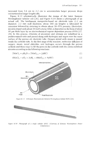
Figure 8.1 3 schematically illustrates the design of the latest Siemens
Westinghouse tubular cell [26], and Figure 8.14 shows a photograph of an
actual cell. The lanthanum manganite-based air electrode tube (2.2 cm
diameter, 2.2 mm wall thickness, about 180 cm length) is fabricated by
extrusion followed by sintering to obtain about 30-3 5% porosity. Electrolyte,
zirconia doped with about 10 mol% yttria (YSZ), is deposited in the form of about
40 pm thick layer by an electrochemical vapour deposition process (EVD) [27,
281. In this process, chlorides of zirconium and yttrium are volatilised in a
predetermined ratio and passed along with hydrogen and argon over the outer
surface of the porous air electrode tube. Oxygen mixed with steam is passed
inside the cathode tube. In the first stage of the reaction, molecular diffusion of
oxygen, steam, metal chlorides, and hydrogen occurs through the porous
cathode and these react to fill the pores in the cathode with the yttria-stabilised
zirconia according to the following reactions:
2MeC1, + yH20 = 2Me0,/2 + 2yHCl (1)
4MeC1, + yo2 + 2yH2 = 4Me0,/2 + 4yHC1 (2)
Interconnection
\ Fuel Electrode
Figure 8. I3 Schematic illustration ofa Siemens Westinghouse tubular SOFC/26].
Figure 8.14 Photograph of a single tubular SOFC. (Courtesg of Siemens Westinghouse Power
Corporation.)